Now more than ever, the blooming of the Internet of Things (IoT) has been putting emphasis on the longevity of battery life. Every IoT node demands a battery to operate. A household of two people can have anywhere from 20 to 60 batteries in use at any time, and consumers can’t be burdened with the need to change batteries all the time. Key parameters used by system designers to calculate battery lifetime can include the active, sleep and hibernate currents of the central controlling unit, such as an MCU and other peripheral devices such as Bluetooth and sensors.
However, this is far from enough. A power supply itself is the beating heart of the system, supplying energy that feeds into every functional block of the system. Vendors have been relentlessly rolling out various new low power techniques embedded in MCUs, sensors and various digital modules. However, without the efficient and reliable power supplies, the system can very much be mal-nurtured and starved to death by draining batteries faster than expected.
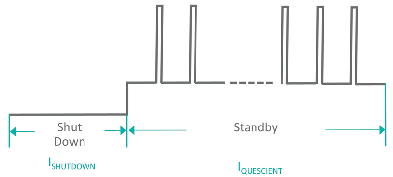
Long battery life can’t be achieved without careful consideration of the nuts and bolts of the power system design. High efficiency power supply is paramount to preserve battery life.Here is why: Most IoT node devices have the power profile outlined in Figure 1. The devices stay on the shelf at shutdown mode until consumers purchase them and deploy them to operation. The devices spend most of their lifetime at standby mode and wake up to send data through Internet Protocol only once a while.
Click image to enlarge
Figure 1: Power Profile of IoT Node Devices
Take a home security system, for example, which is at standby mode most of its lifetime and gets activated based on users’ activities. The active current consumption of the system is definitely critical to extend battery life, but not as critical as the standby current of each component. And what usually contributes the most to the standby power consumption in the whole system? The power supplies.
The heart of a supply
In most cases, the heart of a low, keep-alive power supply is a regulator. It can be a switching regulator to boost up or buck down the voltage, or it is can be a low drop out (LDO). In some complicated cases, it can be a PMIC that encompasses multiple power architectures and even a charger. During the standby mode, the power consumption is defined by quiescent current, also often referred to as IQ. During light load operation, quiescent current can make a great impact on the power transfer efficiency of the system as well.
When quiescent current is mentioned, most engineers think about the current required to bias a device—a simple concept. However, this concept becomes a little more complicated when we apply it to power supplies.
Switching Regulators and LDOs
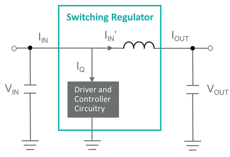
•DC-DC switching regulator: Quiescent current is the minimum amount of current for the converter to stay alive when it is not in use: no switching and no load, but it is enabled. It is the nominal current used while “on” in a minimal state. The IC is turned on and ready to work. Quiescent current is the steady-state current drawn by the IC, and all the quiescent goes to the ground. The overall input drawn by the regulator should be the total of the quiescent current (IQ) and the input inductor current (IIN’), as shown in Figure 2. The IQ does not change with the load, but the input inductor current is decided by the load and the conversion efficiency.
Click image to enlarge
Figure 2: Quiescent Current in Switching Regulators
For example, during a light load standby condition, let us take VIN = 12V, VOUT = 3.3V, Inductor current IIN’ = 60µA, IOUT = 200µA
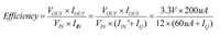
This means that low quiescent current directly translates to high conversion efficiency, especially at a light load. For example, for a converter with IQ = 15µA, the efficiency based on the formula above is 73%, and a converter with 30µA IQ bears an efficiency value down to 61%. Lower efficiency means more power dissipation and shorter battery life.
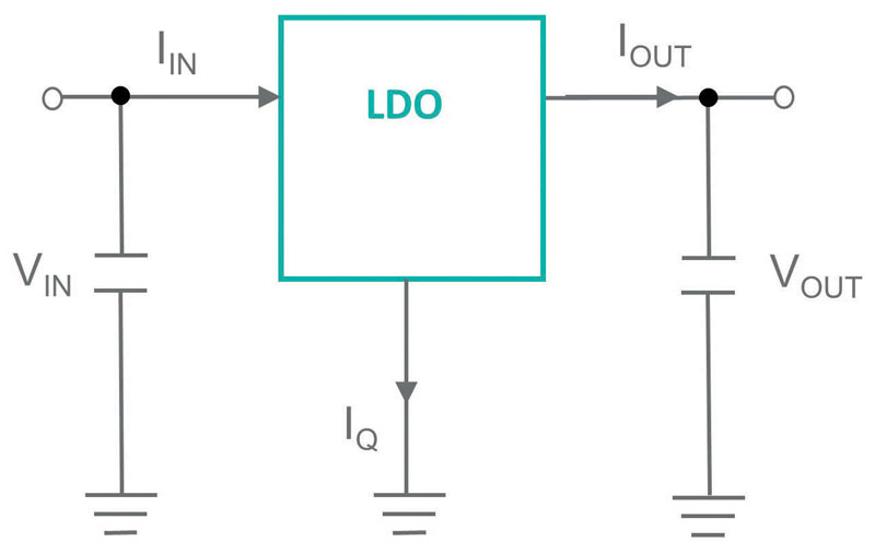
•LDO Regulator: Unlike switching regulators, we can take out the duty cycle dependency out of the quiescent current calculation. It is simply the difference between the input current and the output current, as shown in Figure 3. Similar to switching regulators, quiescent current consists of bias and the gate drive current.
Click image to enlarge
Figure 3: Quiescent Current in Switching Regulators
The conversion efficiency of an LDO can be summarized by the equation below.
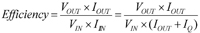
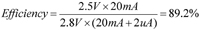
The low quiescent current, along with the low dropout voltage, are necessary to maximize the conversion efficiency. For example, the MAX1725 LDO from Maxim has a quiescent of 2µA and dropout voltage of 300mV. For 2.5V output voltage with 5mA output current, the input voltage needs to be at least 2.8V for the part to regulate. The conversion efficiency is calculated as:
Both quiescent current and dropout voltage contribute to the efficiency curve and an LDO. The lower the output current is, the more quiescent current can impact the conversion efficiency
Quiescent Current vs. Shutdown Current
There have been a lot of questions raised on the difference between quiescent and shutdown current. They can be confused from time to time. Shutdown current is when the device is “asleep” and not ready to work, while quiescent current is the nominal current used while the IC is “resting” and ready to work. The system is in an idle state and waiting for something to happen. Designers usually use quiescent current to gauge the power dissipation of a power supply at light loads, and use shutdown current to calculate the battery lifetime if the device is turned off yet has the battery connected to the regulator.
Real-world application examples include when the following occurs: the charger is not charging the phone but is still plugged into the wall; the wireless mouse is not in use but not yet switched off; the car is turned off but the head unit is still running. In many battery-powered applications, it is the current drawn from the battery in a standby condition with minimum load to drive.
Both quiescent and shutdown currents matter because consumers do not want the charger to be heated up by excessive power dissipation, nor do they want to change the battery every week.
Start with the power profile
In the pursuit of designing a device with the longest battery life, designers need to first start with sketching the power profile of the end product in great detail. You can choose the processors and digital peripherals with the best low power specs, but victories can’t be claimed until the right power regulator specs are locked down. In low power applications, never underestimate the specs and condition of quiescent current because it can be the main contributor to the overall power consumption of the system.
 PDF
PDF