Op amps connect sensors to the rest of the system
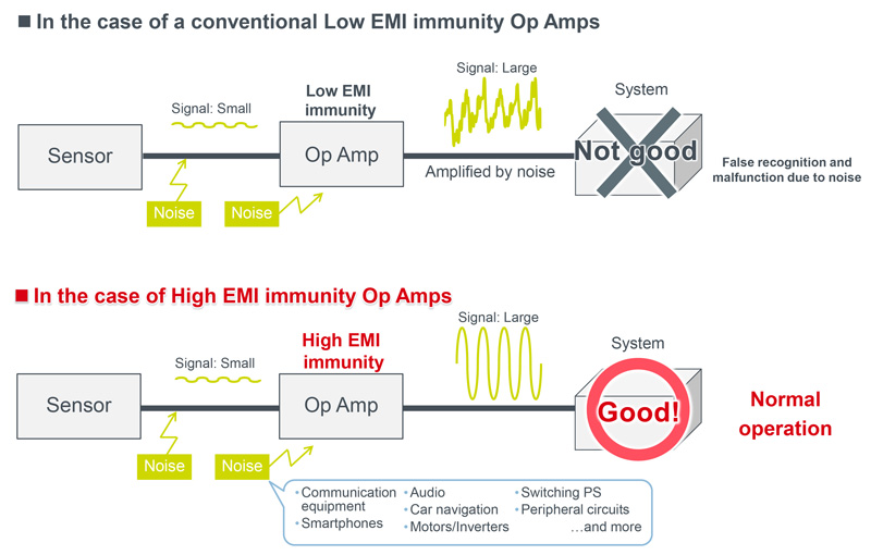
Figure 1: EMI immunity of op amps affects system operation
There are growing requirements in many industries for sensing technologies for measuring and control instruments, or for managing small signals. Op amps connect the sensor to the rest of the system.
However, today’s systems have much higher component densities, leading to increased noise levels. Installing countermeasures against noise to prevent devices that manage small signals from malfunctioning represent a significant challenge. Since it is difficult to verify the design of noise immunity characteristics, a cycle of design, assembly, and evaluation is often repeated many times.
Op Amps
Op amps amplify weak sensor signal outputs to a voltage level that can be recognized by A/D converters. A microcontroller (MCU) controls the circuit based on the output signals from the op amps (and comparators). During the voltage amplification, the focus is on the noise specification of the op amps themselves. When external noise is coupled onto the signal path of the sensor output or the op amp, the noise is directly amplified by the op amp if its noise immunity is not sufficiently high (Figure 1). As a result, a false recognition or malfunction of the MCU may occur, causing a malfunction of the system.
As PCB densities increase, op amps become more susceptible to external noise from the surrounding electric system. Therefore, there is a trend towards electronic components with a higher noise immunity, especially for electronic control units (ECUs) or inverters that require high reliability.
Countermeasures Against Noise
It is important for noise countermeasures that electronic components do not interfere with other parts of equipment and retain their original performance, even if other devices interfere with them. Both of these properties should be compatible in countermeasures against noise, they are referred to as EMC (Electro Magnetic Compatibility). EMC can be categorized into EMI and EMS. EMI (Electro Magnetic Interference) represents how much the electromagnetic waves emitted by electronic equipment containing semiconductors can affect other components or equipment. EMS (Electro Magnetic Susceptibility) is an indicator of how much external electromagnetic waves (noise) is affected by external influences.
When taking countermeasures against noise, all components of the wiring, resistance, capacitance, and inductance must be considered, not only for the op amps themselves, but also for the power and ground traces connected to the op amps. Development of high performance simulators has advanced recently, but they still cannot cover detailed characteristics, including the parasitic capacitance and inductance unique to each process. The strength of noise immunity is eventually determined based on the knowledge, experience, and intuition of designers. These factors make EMC compliant design even more difficult.
Aiming to prevent op amps from malfunctioning without taking special countermeasures, ROHM has developed the “EMARMOUR” series of op amps, which has improved noise immunity. EMARMOUR products utilize ROHM’s vertically integrated system and achieve noise immunity with minimal fluctuations in the output voltage over the entire noise frequency band, as confirmed by international noise evaluation tests.
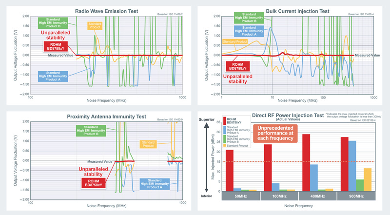
In 2017, ROHM developed bipolar op amps that are ideal for automotive electric systems employing automotive sensors in severe environments, such as automotive power trains and engine control units. Now, ROHM has applied the same technology to CMOS op amps, further improving noise immunity. Developed as part of the EMARMOUR series op amps BD8758xY, the new models achieved an improved performance in four international noise evaluation tests (ISO 11452-2 Radio Wave Emission Test, ISO 11452-4 Bulk Current Injection Test, ISO 11452-9 Proximity Antenna Immunity Test, and IEC 62132-4 Direct RF Power Injection Test) conducted in ROHM’s own anechoic chamber (Figure 2). In the ISO 11452-2 radio wave emission test, the output voltage of conventional products can fluctuate by ±300mV or more across the entire noise frequency band, while ROHM’s latest products achieve noise immunity that limits variation to less than ±10mV.
Click image to enlarge
Figure 2: New CMOS op amps, BD8758xY four international noise tests evaluation results
Achieving High EMI Immunity Analog ICs
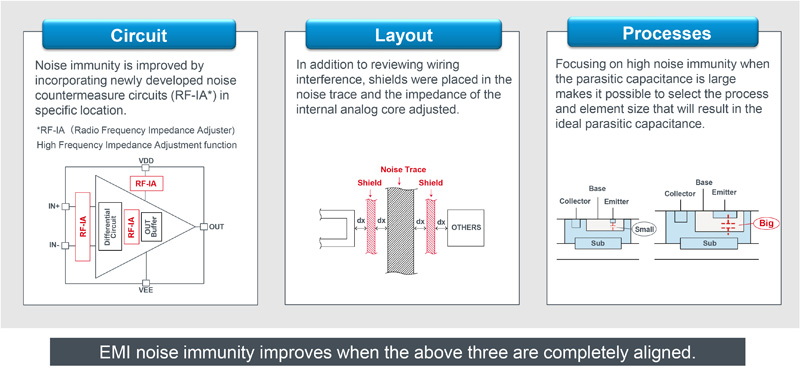
Achieving high EMI immunity in the EMARMOUR series requires integration of three specific analog technologies: circuit design, layout, and process technologies (Figure 3).
Click image to enlarge
Figure 3: Three technologies required for the achieving high EMI immunity analog ICs
First, in circuit design technology, an RF-IA (Radio Frequency Impedance Adjuster) has been developed as a circuit for countermeasures against noise. Parasitic R, C, and L exist even in the wiring from the IC pins to the chip. As the frequency is increased, there is a resonance point where the parasitic C and L cancel each other, resulting in minimum impedance (resonance frequency). Since this resonance makes the op amp more susceptible to external noise, noise immunity tends to decrease. However, the original characteristics of the op amp may be disturbed if a filter circuit is installed. ROHM’s new RF-IA circuit for countermeasures against noise. This circuit allows an optimum impedance adjustment to prevent a noise peak such as resonance in high frequency range as EMC noise, while retaining the original characteristics of the op amps. Noise immunity is improved by incorporating an RF-IA equipped with a function that operates only on high frequency noise, such as EMC noise, and attenuates it over the entire frequency band as necessary.
Next, in layout technologies, chip layouts inside the ICs have been reviewed completely. To improve the noise immunity, the shielding is extended around noise traces that are affected by noise, while the interference between wiring is reviewed. From the impedance of the wiring connected to the internal analog core to every single line of wiring, the layouts have been thoroughly reviewed in detail.
To improve noise immunity, it is important that op amps are resistant to noise at the level of the transistor elements. Noticing that larger parasitic capacitance leads to higher noise immunity, ROHM has selected the processes and the element sizes so that the optimal parasitic capacitance can be achieved.
ROHM employs its own integrated production system from product planning to circuit design, layout, trial product evaluation, and test development. Under close cooperation, elaboration of the circuit design and the element layout has been conducted in the development process, while elaboration of the parasitic capacitance and the element shapes has been conducted in the manufacturing process. By repeating meticulous reviews in each process and optimally integrating measures for improvement, ROHM has aligned these three technologies to develop op amps with improved EMI immunity.
EMARMOUR Series Impact
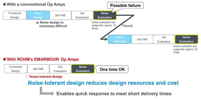
Using EMARMOUR series products cuts the design resources and time required for countermeasures against noise significantly (Figure 4). Typically, a PCB design is carried out in the order of the function design, EMC compliant design, system assembly, system evaluation, and noise evaluation. However, it is difficult to verify the noise design. Even if the system evaluation result is acceptable, the noise evaluation may fail due to an insufficient noise immunity in the op amp. This leads to repeating the design stage where the noise level needs to be suppressed. For example, if a noise peak occurs at 350 MHz in a test with a noise frequency range from 200 MHz to 1,000 MHz, an RC filter may be added as an external block to suppress the peak, possibly with a metal plate shielding the entire IC. However, even if the noise peak at 350 MHz could be suppressed with external parts, a new peak may occur in a completely different frequency band, such as at 900 MHz. Therefore, it may be necessary to repeat the cycle of design, assembly, and evaluation many times.
Click image to enlarge
Figure 4: EMARMOUR series merit: the design resources required for the countermeasures against noise can be reduced significantly
Using op amps with high noise immunity, such as the EMARMOUR series, greatly facilitates EMC compliant design. If the noise evaluation is passed first time, no redesigns are required. In addition, peripheral components for countermeasures against noise can be reduced. If a general op amp is used and the noise evaluation fails, it is necessary to improve the noise immunity, for example, by implementing RC filters into the input and output. By using EMARMOUR series components, RC filters to counteract noise can be eliminated and up to 18 parts (when using 4 channel Op Amps) can be eliminated.