Selecting a Low-lq Voltage Reference to Minimize Power Consumption
As electronic circuits improve, they become smaller, more precise and more accurate
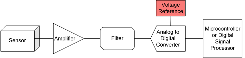
Figure 1: A basic analog-to-digital signal chain
As electronic circuits improve, they become smaller, more precise and more accurate. For a variety of reasons, designers of applications such as industrial automation and medical are under even more pressure to deliver a circuit that is both accurate and has low power consumption.
Many applications with these circuits use analog sensors, which generate a signal that is communicated digitally to users via a basic signal chain, illustrated in Figure 1.
There are often more components included in the signal chain than just those shown in Figure 1, including multiplexers and analog-to-digital converter drivers. Adding more components draws more current and dissipates more power, but is often required for increased accuracy or to enable circuit functionality.
One of the necessary components is a voltage reference. An analog-to-digital converter uses a voltage reference to generate its digital output code. Many analog-to-digital converters have an integrated voltage reference, but analog-to-digital converters that are more precise require voltage references that are stable over temperature, time and many other parameters, to a level that only a discrete voltage reference can provide. Each voltage reference design has different parameters and different power consumption levels; thus, choosing the best voltage reference for your design can have significant effects on the accuracy and power consumption of your circuit.
Series voltage reference parameters and selections
The most common types of voltage references paired with an analog-to-digital converter are series and shunt voltage references. Usually, series voltage references have a significantly lower quiescent current (Iq) and power consumption than shunt voltage references. Series voltage references can also include a shutdown mode, not typically available in shunt voltage references, which can significantly decrease the current consumption of the device. Additionally, series voltage references are typically more precise than shunt voltage references. So if you are looking to choose a voltage reference for a high-accuracy, low-power design, a series voltage reference is the best way to go.
When determining which series voltage reference to use in low-power designs, check the data sheet’s accuracy, durability and power-consumption parameters, especially the initial accuracy, temperature coefficient, 0.1- to 10-Hz peak-to-peak noise, thermal hysteresis and quiescent current. Table 1 shows a few different series voltage references from Texas Instruments (TI), and how their parameters’ typical values compare with a voltage reference output of 3.3 V.

Click image to enlarge
Table 1: Voltage reference parameter comparisons
As you can see in Table 1, each device has different advantages; for example, the REF3333 has a slightly superior temperature coefficient. When designing for low power, however, quiescent current is especially important, which is where the REF35 becomes especially useful. Also notice that the REF35 either meets or improves upon the parameters of the REF3333 and the REF3033, especially when considering the quiescent current.
Low-power design considerations
Battery-powered designs need to have low power consumption so that the power supply is not drained too fast. When designing, quiescent current is the most important voltage reference parameter used to estimate the power consumption of a circuit. Quiescent current is the current needed to operate the voltage reference and all internal aspects of the design when the reference is enabled with no load. Naturally, the lower the quiescent current, the lower the amount of power consumed by the voltage reference. Therefore, choosing a voltage reference with a low quiescent current can optimize the power consumption of your design.
When designing for low power, you can see in Table 1 that the REF3333 has a quiescent current more than 5 times larger than the quiescent current of the REF35, while the REF3033 has a quiescent current over 60 times larger. The REF35 obtains this low quiescent current while still retaining the necessary specifications for a high-accuracy design.
Not only does the REF35 have a quiescent current below 1 µA, it also provides a shutdown mode, which gives you the option to decrease the power consumption of your signal chain even further. While in shutdown mode, the enable pin on the REF35 pulls low. Once this occurs, the quiescent current drops to, at most, 0.1 µA.
A voltage reference such as the REF35 can be instrumental for low-power applications that require high accuracy. Specifically, this type of voltage reference is helpful in lowering the power consumption of a signal chain within a device. As I mentioned previously, high-precision analog-to-digital converters 12 bits or higher often require a voltage reference in order to create accurate digital outputs. Using the REF35 with an analog-to-digital converter such as TI’s ADS7038 can potentially provide a low-power, high-accuracy solution for a signal chain.
Application example: field transmitters
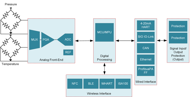
One area where low quiescent current is essential is in field transmitters, which measure pressure, temperature and many other important aspects in industrial settings. They convert real-life phenomena into a digital signal. Figure 2 is a block diagram of a pressure transmitter.
Click image to enlarge
Figure 2: Signal chain for a pressure transmitter– notice the circled voltage reference block
Field transmitters are used in many manufacturing processes. Their continuous and reliable operation is essential to many businesses worldwide.
To observe how voltage reference selection could improve these devices, let’s look at the basic design of a certain type of field transmitter: a 4 to 20-mA field transmitter. These field transmitters are typically two-wire, battery-powered devices where each essential component is placed within one loop of wire, thus allowing the current, typically in the 4 to 20-mA range, to remain constant throughout the whole device. This setup can limit exactly how much current you have available. For this reason, when designing this type of field transmitter device, you are counting each microampere, which can make accurate measurements with a very precise number of bits difficult while staying within your current budget. If you are current-constrained, it can be difficult to justify adding a voltage reference to assist a high-precision analog-to-digital converter. The REF35 voltage reference does not burden the current budget that heavily.
Application example: medical devices
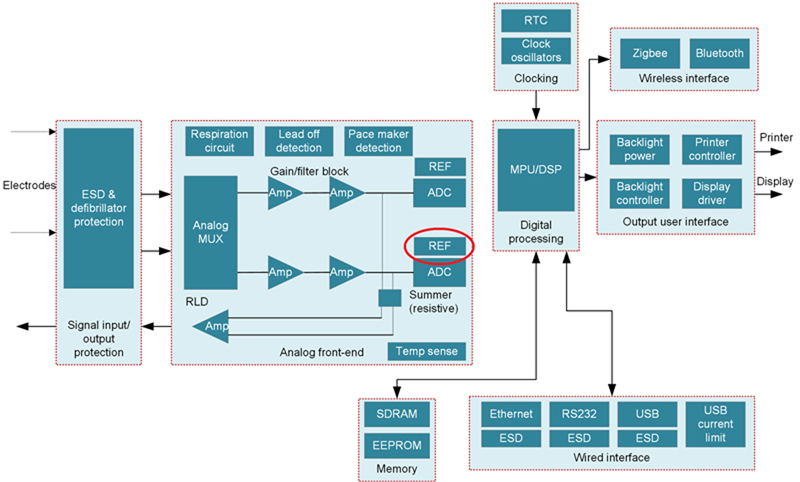
The trade-off between low power and high accuracy is especially pertinent in medical devices, where poor accuracy could have major implications on patient health. For example, an electrocardiogram patch attaches to the skin in order to monitor a heartbeat, notifying the patient of irregularities or other heart-related health parameters that the device can interpret. Patients may wear this device for long periods of time, and it must be on and measuring constantly to provide accurate data to medical professionals. Figure 3 is a block diagram of an electrocardiogram.
Click image to enlarge
Figure 3: An electrocardiogram patch block diagram– notice the circled voltage reference block
To achieve long battery life while also maintaining reliable operation and taking accurate readings, you must carefully choose the components used in the device. An electrocardiogram device often uses a delta-sigma analog-to-digital converter of 24 bits or more, precision that requires a very accurate voltage reference. Users often wear electrocardiogram patches up to a month at a time. Throughout this month, minimizing the amount of charging allows for longer data collection times due to the user removing it less often because of low battery. This, in turn, would improve the quality and accuracy of the recorded data. For this reason, it’s important to keep the amount of current drawn as low as possible.
To illustrate the strength of the low quiescent current present in the REF35, you can compare its current consumption to the REF3040. The quiescent current of the REF35 is 0.65 µA and the quiescent current of the REF3040 is 42 µA. If you were to place either of these voltage references in a medical application, the REF3040 would drain the battery 64.6 times faster than the REF35.
Conclusion
In high-accuracy low-power designs, every component that you choose contributes to the delicate balance of your current budget. When you need a high-precision analog-to-digital converter, you will also need a voltage reference. Careful examination of the parameters defining these voltage references is essential to choosing the best one for your design.
When you must conserve the accuracy of your circuit but don’t have the current budget for a typical voltage reference, using a device such as the REF35 in your signal chain can provide a stable voltage signal while contributing less than 1 µA of quiescent current. This can lead to a design that does not have to sacrifice accuracy for lower power consumption.