Talking to Analog Devices’ Frederik Dostal on SIMO components and their applications.
Like other types of passive components, inductors can be bulky and costly. In some designs, this is not a problem, however more and more designs are becoming space constrained and the requirement for multiple power rails is also a growing trend. Each output usually needs its own inductor, and if there are three or four output voltages required, then the cost and amount of board real estate needed can mount up quickly.
One solution that may help, in some cases at least, is using a Single Inductor, Multiple Output DC/DC converter. These components only require the use of a single inductor to output multiple voltage rails while still maintaining efficiency. The upsides to the technique are quite considerable for suitable applications, such as smart watches or any other small, low-voltage application with multiple voltage inputs. Designs can be a lot smaller and use fewer components, meaning a reduced BoM and less design complexity, as well as a reduction in cost. SIMO components are especially useful for applications that require buck-boost conversion, especially battery-powered devices as the input voltage from the battery drops over time.
Dostal expands on this by saying, “The biggest advantage of SIMO technology is if you need a buck-boost conversion alongside typical low-voltage rails. For example, lithium-ion batteries begin discharging around 3.6 V and as it discharges, it can get down to around 3.0 V. If you need to generate a solid 3.3 V rail, then you need both buck and boost to generate 3.3 V continuously, and this can be done while the buck converters supply other voltages like 1.8 V and 1.2 V, and all with a single inductor.”
Of course, like every other technique there is a trade off and restrictions. In this case, SIMO technology is only really suitable for low-voltage applications. Currently, the maximum input voltage available using SIMO components is around 5.5 V. However, that could change soon, as Analog Devices, and possibly other manufacturers, are working to extend the input voltage range for the component. Further, the output signal is not a perfect DC voltage, as some ripple is introduced when the controller switches between different outputs, although a high frequency operation, a good output capacitor and other design techniques can keep the ripple to an absolute minimum. Finally, the SIMO solution requires a larger silicon footprint than other conversion techniques.
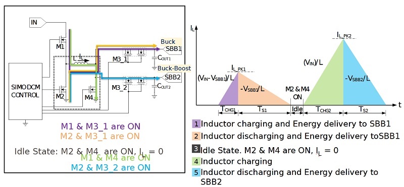
Explaining how SIMO components work using the image above, Dostal says, “The image shows the inductor current over time. In step 1, the inductor is charged up over a certain on-time, leading to energy stored in the inductor. In step 2, we discharge the inductor and feed the energy out to the buck output - a typical buck operation. There is a little bit of idle time and then the inductor is used for the for the buck-boost output. In step 3, the energy is charged up into the inductor for the buck-boost. Then in step 4, the energy is discharged to the buck boost output. It is really only time scheduling the inductor time.”
Analog Devices has used its SIMO technology in both subsystem PMICs and full system PMICs, which include additional integrated functions and features, including battery management (charger and fuel gauging), LDO outputs for noise- sensitive rails, and an on-board sequencer for controlled power-up and power-down. An I2C interface provides the capability to completely customize the power management IC and supports dynamic voltage scaling (DVS) for additional power savings and custom power profiles.
If you are interested in SIMO technology, you can play around with the dedicated SIMO calculator at this location https://www.analog.com/en/design-center/evaluation-hardware-and-software/software/software-download.html?swpart=SFW0019590A

.jpg)