Step by Step Methodology and Solutions for Connecting and Disconnecting a Supply Voltage Line
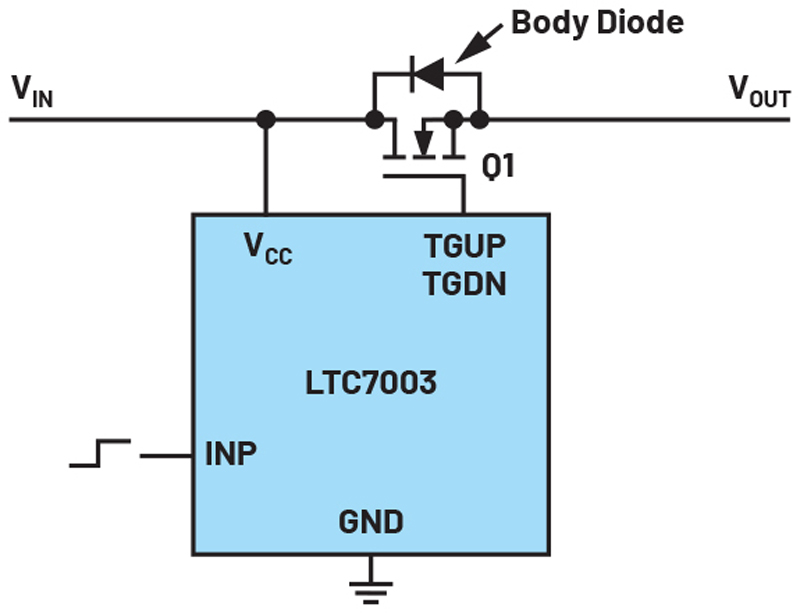
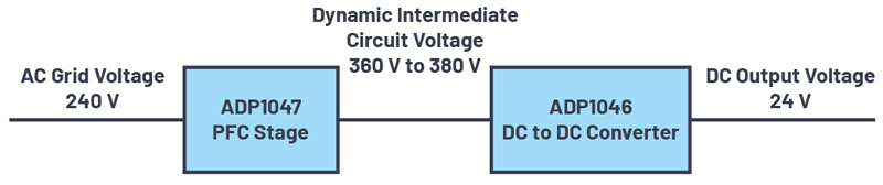
Figure 1. Switching a supply line with an N-channel MOSFET and a separate driver circuit, the LTC7003.
This article discusses the options a circuit designer has to turn on and off supply lines in electronic systems. While the task sounds trivial, there are many things to consider for a successful implementation.
In some electrical systems, disconnecting a supply line is necessary. This may be in the form of cutting off a battery voltage to retain the battery charge or separating a load from a live line, for example. Ideally, a mechanical switch is used for this. However, if switching should occur via an electrical signal, an electronic switch is usually more suitable. Such an electronic switch can be built with a MOSFET as a switching element. In addition to a purely discrete solution with a MOSFET, numerous semiconductor ICs are available for easy implementation of an electronic switch.
First, a decision must be made regarding whether the switching element should be an N-channel or a P-channel MOSFET. Both may be suitable. Compared with a P-channel MOSFET, an N-channel MOSFET has a lower resistance and thus lower losses in the on state. The disadvantage lies in the driving of the N-channel MOSFET. Here, a higher voltage than the available supply line voltage is required for the gate. Hence, the driving IC must contain a charge pump of some sort. A P-channel MOSFET does not require this type of voltage increase. However, there is a large selection of N-channel MOSFETs.
In the next step, a selection is made between having the power switch and the driver in a single housing or using a two-chip solution with the driver circuit in a separate IC and the corresponding MOSFET in a second housing. The already optimized selection of the switch for the driver circuit speaks in favor of integration in one package. The switch is usually well protected through this and thus is not overloaded during operation. The disadvantages of such an all-integrated solution include a smaller offering on the market and higher cost.
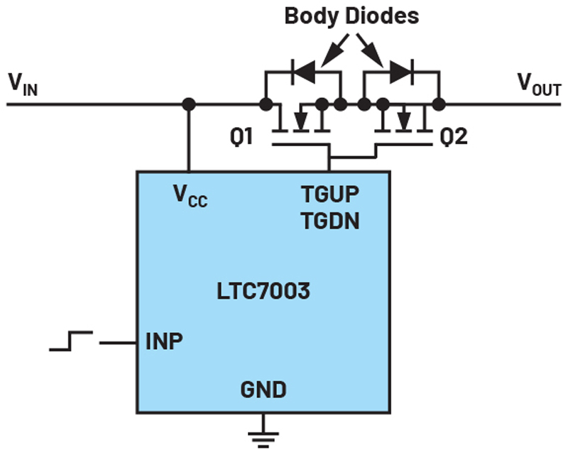
In the third step, a decision must be made regarding whether a single MOSFET is sufficient for a mechanical switch. A MOSFET always has a body diode included. Thus, it can only switch currents in one direction. If an application requires that a line be completely interrupted so that currents cannot flow in either direction, a solution with two MOSFETs connected in series in opposite directions is needed. Figure 2 shows such a switching stage arrangement.
Click image to enlarge
Figure 2. A circuit in which current flow in both directions can be prevented by two N-channel MOSFETs back-to-back.
Finally, the appropriate integrated circuit, that is, the driver for the MOSFET,or the package with the MOSFET and the driver must be selected. This step sounds trivial, but it is quite tedious. Load switches are often sought. As a rule, however, there is no large offering here. Hot swap controllers, electric fuses, surge protectors, ideal diodes, and power path controllers can be used in many cases depending on the application and the additional monitoring functions required. In most of these devices, there is an on/off pin allowing the flow of current to be interrupted when necessary. With the LTspice® simulation tool from Analog Devices, it is possible to check whether the precise behavior of the solution meets the specifications.

Click image to enlarge
Figure 3. An LT spice simulation with an LTC4414 low loss Power Path™ controller as a load switch.
Disconnection of a supply voltage can become complex depending on the application. A special MOS driver IC with an on/off control pin makes this design easier.