Testing these systems requires an understanding of the different possible measurement connections
Understanding wiring configurations and making proper connections is critical to performing power measurements. Although single-phase electricity is used to supply common domestic and office electrical appliances, three-phase alternating current systems are almost universally used to distribute electrical power and to supply electricity directly to higher power equipment.
The principles behind three-phase systems are relatively straightforward, thorough testing of these systems requires an understanding of the differences across the possible measurement connections. Here we provide a quick overview of three-phase systems followed by details on measurement connections and tips for configuring equipment.
A quick three-phase system overview
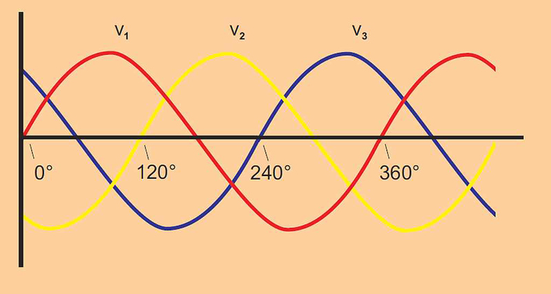
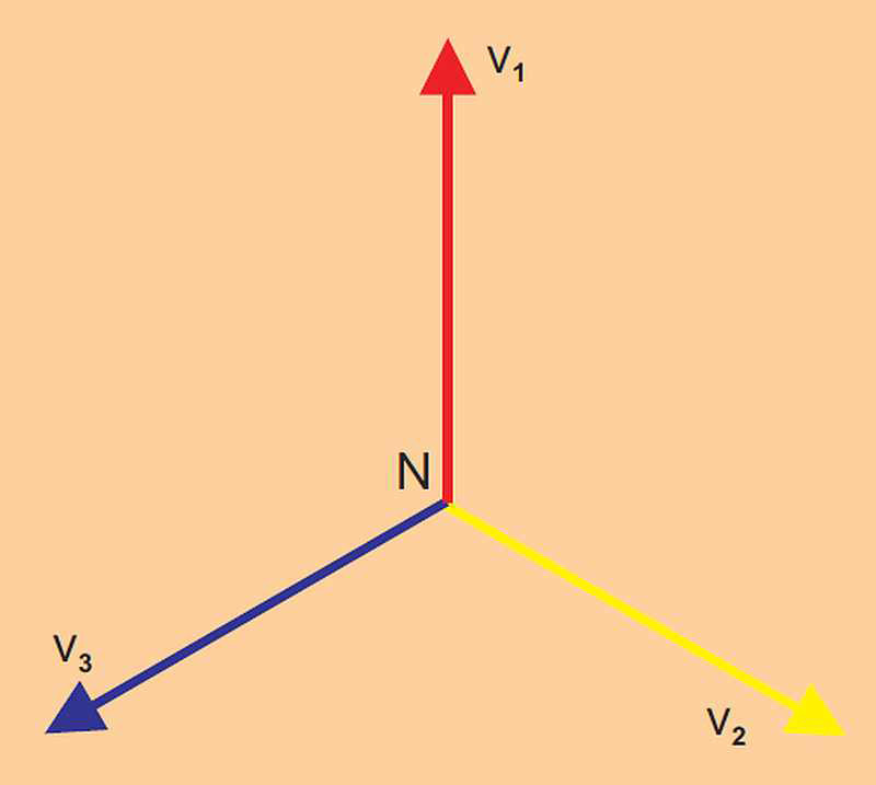
Three-phase electricity consists of three AC voltages of identical frequency and similar amplitude. Each AC voltage phase is separated by 120° from the other. This separation can be represented by both a waveform and a vector diagram as shown in Figure 1.
Click image to enlarge
Figure 1
Figure 1a & b. Three-phase power can be represented by both waveforms and a vector diagram.
Click image to enlarge
Figure 1b
Figure 1a & b. Three-phase power can be represented by both waveforms and a vector diagram.
There are two main reasons for using three-phase systems:
1. The three vector-spaced voltages can be used to create a rotating field in a motor. As a result, motors can be started without the need for additional windings.
2. A three-phase system can be connected to a load so that the amount of copper connections required – and the transmission losses – are one half of what they would otherwise be.
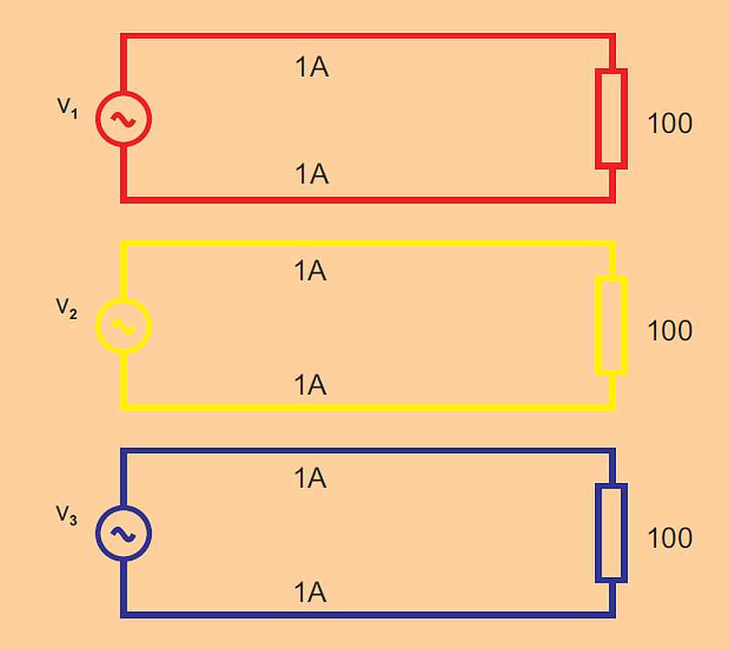
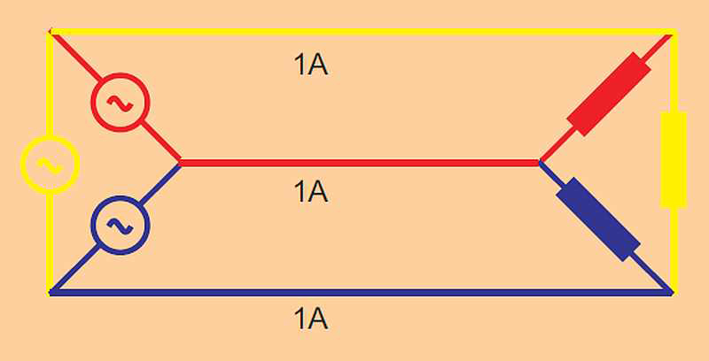
To illustrate the second point, in Figure 2 three single-phase systems are each supplying 100W to a load. The total load is 3 x 100W = 300W. To supply the power, 1 amp flows through six wires resulting in six units of loss.
Click image to enlarge
Figure 2. Three single phase power supplies result in six units of loss.
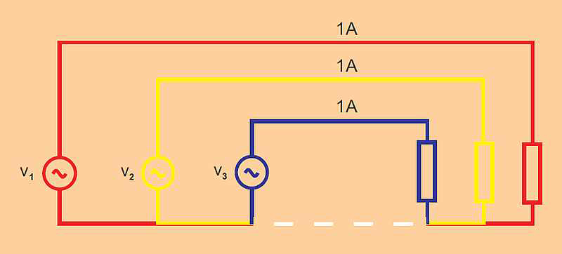
But the story is much different when the three supplies are connected to a common return. When the load current in each phase is the same the load is balanced. With the load balanced and the three currents phase shifted by 120° from each other, the sum of the current at any instant is zero and there is no current in the return line as shown in Figure 3.
Click image to enlarge
Figure 3. With a three-phase supply, the load is balanced for three units of loss.
In a three-phase 120° system, only three wires are required to transmit the power that would otherwise require six wires. One half of the copper is required and the wire transmission losses are halved.
Wye or Star Connections
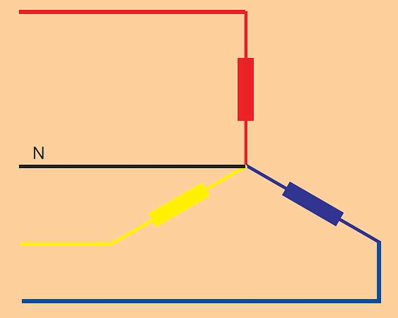
A three-phase system with a common connection is normally drawn as shown in Figure 4 and is known as a wye or star connection. The common point is called the wye, star or neutral point. This point is often grounded at the supply for safety reasons. In the real world, loads are not perfectly balanced and a fourth neutral wire is used to carry the resultant current. The neutral conductor may be considerably smaller than the three main conductors.
Click image to enlarge
Figure 4. This is a typical wye or star connection for three phase with four wires.
Delta Connection
The three single-phase supplies discussed earlier could also be connected in series. The sum of the three 120° phase shifted voltages at any instant is zero. If the sum is zero, then both end points are at the same potential and may be joined together. The connection is usually drawn as shown in Figure 5 and is known a delta connection.
Click image to enlarge
Figure 5. This is a typical delta connection for three phase with three wires.Wye and Delta Comparison
The wye configuration is used to distribute power to everyday single-phase appliances found in the home and office. Single-phase loads are connected to one leg of the wye between line and neutral. The total load on each phase is shared out as much as possible to present a balanced load to the primary three-phase supply.
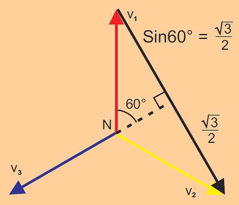
The wye configuration can also supply single- or three-phase power to higher power loads at a higher voltage. The single-phase voltages are phase to neutral voltages. A higher phase-to-phase voltage is also available as shown by the black vector in Figure 6.
Click image to enlarge
Figure 6. A higher phase to phase voltage is available as shown by the black vector, or V phase-phase = √3 x V phase-neutral
Power Measurements
Power is measured in AC systems using wattmeters. Modern digital sampling wattmeters, including higher-end power analyzers, multiply instantaneous samples of voltage and current together to calculate instantaneous watts and then take an average of the instantaneous watts over one cycle to display the true power. Wattmeters provide accurate measurements of true power, apparent power, volt-amperes reactive, power factor, harmonics and many others over a broad range of wave shapes, frequencies and power factor. In order for power analyzers to give good results, you must be able to correctly identify the wiring configuration and connect the analyzer's wattmeters correctly.
Blondel’s Theorem: Number of Wattmeters Required
In a single-phase system there are just two wires. Power is measured using a single wattmeter. In a three-wire system, two wattmeters are required. While there are cases where it is useful to have an additional wattmeter, in general, you can use the following rule: number of Wattmeters Required = No. of Wires -1
Single-Phase Wattmeter Connection
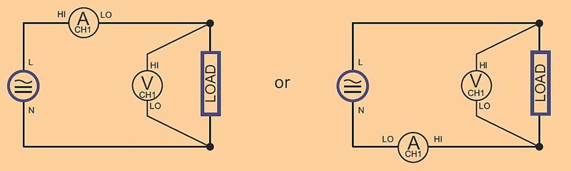
For single-phase measurements, only one wattmeter is required as shown in Figure 7. The system connection to the voltage and current terminals of the wattmeter is straightforward. The voltage terminals of the wattmeter are connected in parallel across the load and the current is passed through the current terminals which are in series with the load.
Click image to enlarge
Figure 7. Connections for single-phase, two-wire and DC measurements.Single-Phase, Three-Wire Connection
In this system, the voltages are produced from one tapped transformer winding and all voltages are in phase. This is common in North American residential applications, where one 240V and two 120V supplies are available and may have different loads on each leg. To measure total power and other quantities, connect two wattmeters as shown in Figure 8.

Click image to enlarge
Figure 8. Connections for single-phase measurements with three wires.
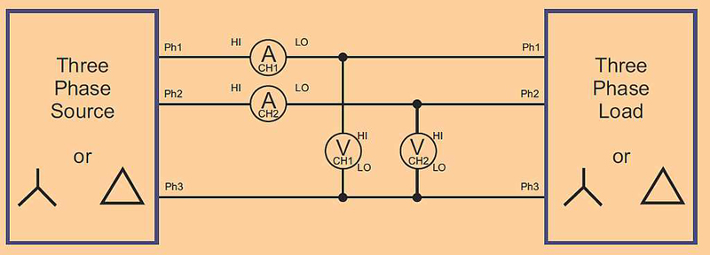
In cases where three wires are present, two wattmeters are required to measure total power. Connect the wattmeters as shown in Figure 9. The voltage terminals of the wattmeters are connected phase to phase.
Click image to enlarge
Figure 9. Connections for three-phase, three-wire measurements with two wattmeters.
Although only two wattmeters are required to measure total power in a three-wire system as shown earlier, it is sometimes convenient to use three wattmeters. In the connection shown in Figure 10, a false neutral has been created by connecting the voltage low terminals of all three wattmeters together.
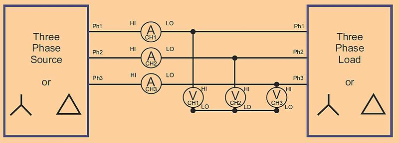
Click image to enlarge
Figure 10. Connections for three-phase, three-wire measurement using three wattmeters.
Three-Phase, Four-Wire Connection
Three wattmeters are required to measure total watts in a four-wire system. The voltages measured are the true phase-to-neutral voltages. The phase-to-phase voltages can be accurately calculated from the phase-to-neutral voltages’ amplitude and phase using vector mathematics. A modern power analyzer will also use Kirchoff’s law to calculate the current flowing in the neutral line.
The instantaneous power measured by a wattmeter in a three-wire wye system as shown in Figure 11 is the product of the instantaneous voltage and current samples.
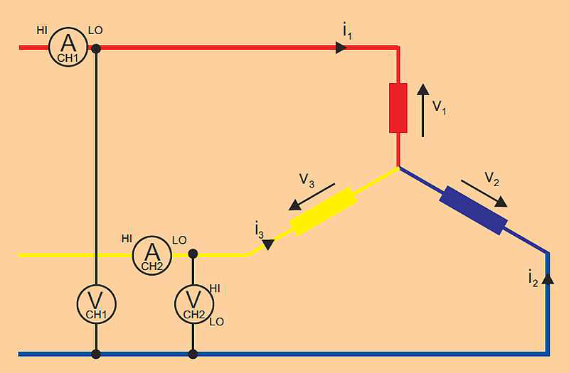
Click image to enlarge
Figure 11. Three-wire wye system measurements.Wattmeter 1 reading = i1 (v1 - v3)
Wattmeter 2 reading = i2 (v2 - v3)
Sum of readings W1 + W2 = i1v1 - i1v3 + i2v2 - i2v3
= i1v1 + i2v2 - (i1 + i2) v3
(From Kirchoff’s law, i1 + i2 + i3 = 0, so i1 + i2 = -i3)
2 readings W1 + W2 = i1v1 + i2v2 + i3v3 = total instantaneous watts
Configuring Measurement Equipment
As discussed earlier, for a given number of wires, N, N-1 wattmeters are required to measure total quantities such as power. You must make sure you have sufficient number of channels and have them connected properly.
Modern multi-channel power analyzers can calculate total or sum quantities such as watts, volts, amps, volt-amperes and power factor directly using appropriate built-in formulas. The formulas are selected based on the wiring configuration, so setting the wiring is critical to get good total power measurements. A power analyzer with vector mathematics capability will also convert phase to neutral (or wye) quantities to phase to phase (or delta) quantities. The factor √3 can only be used to convert between systems or scale the measurements of only one wattmeter on balanced, linear systems.
Understanding wiring configurations and making proper connections is critical to performing power measurements. Being familiar with common wiring systems, and remembering Blondel's Theorem will help you get the connections right and deliver results you can rely upon.