Technology-Driven Optimization for Power and Thermal Tradeoffs
How small architecture changes early in the design phase can have a huge impact on the power consumption of the end product
Traditionally the key concerns and optimization targets in chip development have been summarized as “PPA”—performance, power and area. Depending on the application domain, the relative weighting of those three design objectives can vary greatly. In mobile devices, power has been key for quite some time. In fitness trackers, medical devices, and other products for the IoT edge, power may be so scarce and important that harvesting of power during operation is critical. In contrast, for wall-outlet-powered devices like servers and most consumer electronics, power may be less of an issue, but thermal effects become critical. Also, can a given package deal with the energy consumption appropriately or will parts of the devices have to shut down to prevent overheating? This links back to mobile applications as well, where in some cases, for instance AnTuTu, benchmarks simply started dropping to lower levels at a later time during operation as thermal limits were reached and some of the processing power needed to be switched off.
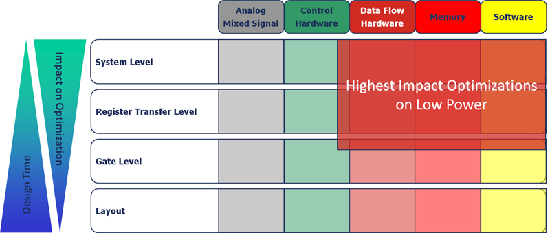
As illustrated in Figure 1, looking at the various components of a chip from analog and mixed-signal circuitry, control hardware, dataflow hardware, memory, and software, the last three typically have the biggest impact on power consumption—especially at higher levels of abstraction. Designers make several decisions that significantly influence the power consumption of the design. Micro architects who take an algorithm defined in C or SystemC and decide how to implement it face various high-impact areas for low-power optimization, such as bit-width selection, tradeoffs between performance and voltage and energy consumption, optimization of the design activity, trading area versus energy consumption, memory optimization, clock gating, voltage scaling and hardware/software tradeoffs. For instance, if specific functions can be moved from software to hardware at the architectural level, significant power reduction can be achieved. System-level models are required but relatively easy to get to, they allow dealing with a reasonable amount of data at high simulation speed but limited accuracy.
As the design proceeds towards implementation at the register-transfer level (RTL), the number of options to reduce the energy consumption is still quite high, allowing reasonable overall leverage. Specific areas of the design can be dynamically switched to low-power modes, trading performance versus energy during execution. Popular methods are reduced clocking or full clock gating of areas in the design. Optimized resource sharing, isolation of operands and optimized coding of controller and bus states can contribute to reduce the capacities to be switched. In principle, architecture changes are still possible at this level. For example, a user may change the number of multipliers to reduce switching via utilization of correlation between subsequent data in a data stream. However, users often focus completely on functional verification during this phase. Also, simulation times are becoming significant and the actual effort to design the RTL often prohibits focus on energy optimization at this level of abstraction.
After logic synthesis for the gate-level netlist, dynamic energy consumption can be determined fairly accurately based on the design activity. At this level, design teams can utilize optimizations minimizing the capacities that have to be driven by the most active nodes in the design. Also, energy consumption can be optimized using a balance of path delays to avoid spikes and spurious transitions and re-timing. The accuracy of power estimation is quite high at this level of abstraction, but the amount of data to be dealt with increases greatly. Even if the gate-level simulation is performed without back-annotated timing, users have to take into account significant simulation times.
Once design teams have reached the actual layout phase, which leads to the delivery of a GDSII tape for actual implementation, sufficient data is available to allow accurate simulation and estimation of energy consumption. Depending on the estimates at this level of abstraction, design teams can still do transistor sizing and layout rearrangements to achieve optimization based on placement and interconnect. The accuracy at this level of abstraction is very high, but the amount of data to be processed and the simulation speed are so limited that typically only a small number of test vectors can be used for analysis. The leverage on energy consumption is comparatively low as no major design changes, such as adjustments to the number of arithmetic resources, can be made anymore.
Bottom line, power optimization faces a dilemma: While decisions at higher levels of abstraction at the system level have the highest impact, they are made based on the least-accurate data available for the design at that point in time. In contrast, when the most accuracy is available at the layout level, the impact of changes based on that data is relatively small, and simulation times take a very long time. To address that dilemma, users need to be offered techniques that allow combination of deep simulation cycles including software execution, for example, with accurate information derived from semiconductor technology library definition.
Bridging Abstraction Levels
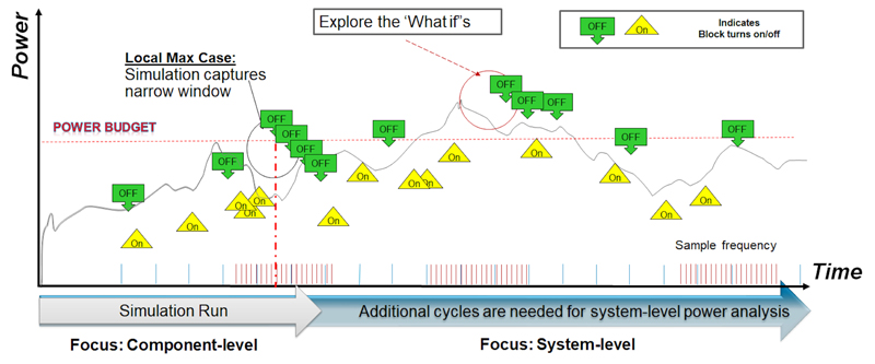
As illustrated in Figure 2, if not enough cycles are executed for a design, including the software running on its processors, users are at risk of getting stuck in a local minimum. Deep cycles are needed to find the actual worst-case power consumption.
Click image to enlarge
Figure 2 – The need for “deep cycles”
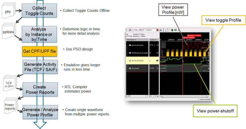
Using emulation in combination with power estimation from RTL or gate-level, it is possible to bridge abstraction levels today. With emulation solutions, like the Cadence Palladium Z1 Enterprise Emulation Platform, users can collect large amounts of activity data in a relatively short amount of time and connect them to implementation flows. Even though emulation allows execution in the MHz range when compared with simulation that runs in the Hz range, identifying the correct hotspots is best achieved by starting with more abstract, course-grain activity information, like raw toggle counts for the design, where each toggle counts as one to achieve early-stage estimation.
After refining the area of interest, weighted toggle counts can be used. They operate with weights on different nets, for instance, when treating a memory write-enable toggle as more significant for power consumption than a NAND gate input toggle. This achieves higher accuracy. The highest accuracy can ultimately be achieved using the SAIF toggle-count format at fine-grain accuracy. This format can then be consumed by power calculators like the Cadence Joules RTL Power Solution, which takes low-level technology data from .lib definitions into account.
Figure 3 shows the resulting design flow and an example of a power profile debug environment that includes toggle count and visualization of a power shutoff. Design teams can shift the power optimization steps to a much earlier time in the design cycle using either: (1) A combination of activity data derived from the RT-level with estimates of power consumption from RTl using technology information in .lib files, or (2) Using activity information derived from the gate-level with annotated power information to which .lib files can be annotated directly. This saves expensive redesign cycles as opposed to discovering power issues that need to be corrected at a later stage of the project. It also allows designers to optimize power with software running on processors that are part of the design and can heavily impact the dynamic power consumption.
Click image to enlarge
Figure 3 – Cadence Dynamic Power Estimation Flow
Utilizing Standard Formats Like IEEE 1801
IEEE 1801/UPF is an IEEE standard that specifies power intent using either a separate file via TCL-style commands or power intent written directly in the hardware description via language attributes and HDL packages. The standard defines the different power domains in a design and various tools, such as simulation and emulation, can consume IEEE 1801 compliant code to help users represent the power intent. When considering a design with four power domains—three of which are switchable and one that is switchable but also has high- and low-voltage states—users will have to test nine basic states and 24 modes of operation.
This testing can be done in simulation and emulation. Although some of these modes of operation may not be consequential, when paired with hundreds or even thousands of functional tests, one can begin to understand the impact of overlaying low power on the verification problem. It becomes very desirable to enlist the raw computational power of emulation, augmenting what can be done in simulation.
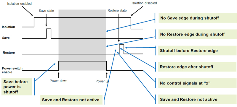
A typical functional test would be augmented to include the power control signals. For power shutoff verification, for instance, the cycles for asserting isolation begin the sequence, followed by state retention, and then finally a power shutdown of the domain must be asserted to verify operation. Figure 4 calls out a number of checks that ought to be performed.
Click image to enlarge
Figure 4 – Checks to be performed during a power off/on scenario
When evaluating emulation support for IEEE 1801, users should check for specific capabilities that have specific implications to them. For instance, memory randomization during shutdown and power-up, control over the read value during the power-off state, non-volatile memory state retention, and the freezing of data on retention are important when it comes to making the low-power verification repeatable. Users should be aware that in emulation—such as when using the Palladium Z1 platform—a 10%-20% capacity overhead associated with IEEE 1801-driven low-power verification exists due to the automatic insertion of logic to handle power domain management. The emulation workflow for IEEE 1801 power verification in the Palladium Z1 platform requires a change to existing user code to include that IEEE 1801 power intent file during the compilation stage, and the rest of the flow is fully automated.
User Experiences
For dynamic power analysis, one recent example was shared at CDNLive in Silicon Valley in a presentation by Theodore Wilson, technical lead for Architecture Co-Verification at Microsemi, called, “Rapid Turns with Palladium and Joules”. The key metric Microsemi was trying to optimize was “power analysis is throughput—the time from activity trace to actionable power reports.” By combining the Palladium Z1 platform with Joules power estimates, Microsemi was able to do gate-level runs as soon as RTL was functional… all of it early, accurate and precise. Other customers, such as Texas Instruments, previously reported results of the emulation to implementation flow to be within 96 percent of their expected power consumption. By doing longer runs in emulation when compared to simulation, they were able to detect unexpected power conditions as the design was run on emulation with actual software for real use-case scenarios.
Cadence
More information on Microsemi case study http://bit.ly/2J0Cspy