Using Rigol’s UltraPower analyzer software
This software, in combination with Rigol oscilloscopes (series DS/MSO2000A, DS/MSO4000 or DS6000) allows customers to set up small test systems, which represent a reasonably priced alternative for measuring switching power supply parameters during the development phase.
Switching power supplies are commonly used in both the electronics and consumer industry. For example, you will find switched power supplies in TVs, computers, halogen illuminations and in many other consumer devices. Various parameters of these power supplies have to be measured and compared with limits during the development and also during the production phase. All built-in switching power supplies must be tested and have to be compliant with the European standard IEC61000-3-2.
Similar to the EMI testing (CISPR-Norm) there is also a split between pre-compliance test (mostly during the development phase) und compliance test (Certification). Rigol is now able to offer a very competitive pre-compliance test solution for the EMI field as well as a solution for the “power analysis” area. The test system consists of a special PC software, an oscilloscope, as well as a current probe and a voltage probe for connection with the test object.
There are three areas of measurements implemented in the software:
1. Measurements at the input
- Power Quality
- Harmonics (IEC61000-3-2)
- In-rush Current
2. Measurements at the Switch
- Switch Loss
- Save Operating Area
- Modulation
3. Measurements at the output
- Output Analysis of the Switching Power Supply.
An example will be described hereinafter, the measurement of harmonics and the harmonic current. Before starting with the measurements it needs to be carried some steps.
1. Demagnetization and zeroing of the probes
To ensure the accuracy of the measurement, it must be demagnetized and zeroing-performed (especially in assets) before using the probes.
2. Correction of the time lag between current and voltage measurement channel (channel deskew)
Since a time delay between the voltage and the current probes could occur (channel 1 and channel 2 on the oscilloscope) and thus inaccuracy of performance measurement can be caused by the “channel delay” calibration is required. With the calibration RPA246 adapter and the UltraPower analyzer software calibration can be performed automatically.
For this purpose, a pulse signal is simultaneously recorded with the voltage probe and the current probe and determined by measuring function on an oscilloscope the time difference between two detected signals. The values determined are hereby stored in the software and can used for later measurements. These data can be saved and reloaded the next time you start or the offset calibration must be performed again.
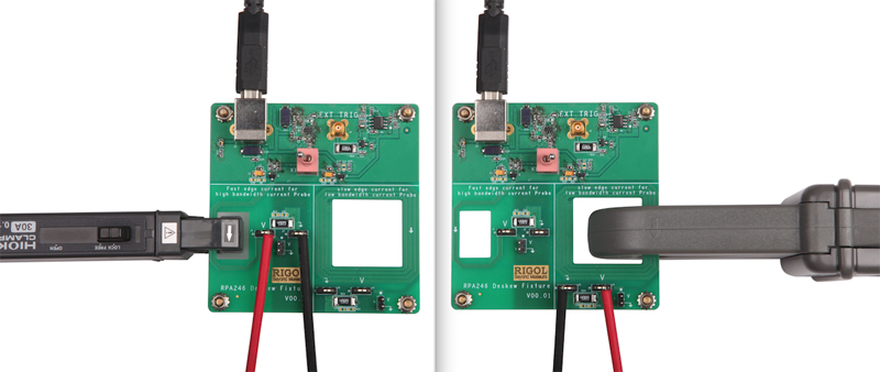
The voltage- / current-supply of the adapter RPA246 correction is provided with an oscilloscope or a PC via a USB cable. There are two connection options (one large and one small current loop), depending which current probe is used (max. cable diameter and max. measuring current). Both possibilities are shown in the Figure 1.
Click image to enlarge
Figure 1: There are two connection options, depending which current probe is used. Small Loop (L), Large Loop (R)
Optimized for Switched Power Supply measurements
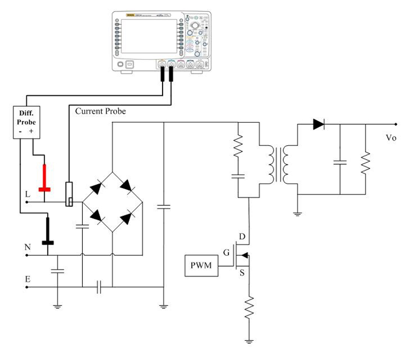
As already mentioned above, the most important measurement tasks which are needed for testing switching power supplies are integrated in Ultra Power Analyzer software. For this purpose, you will find among other things a graph, "online" help, how or where the probes must be connected for the selected measurement. Figure 2 shows a configuration example for the measurement of input parameters, such as power quality, harmonics or In-Rush-Current. The display of the graph, the user can activate by setting tips on / off or off.
Click image to enlarge
Figure 2: A configuration example for the measurement of input parameters
Once all the preparations are done and the test set-up is fixed, you can now begin to perform the measurements. Depending on the selected measuring, some parameters need to be supplemented. The measurement of harmonic currents required as additional information. These are listed below.
1. Main-Frequency:
This information is important because this value is the basis of the assessed harmonics.
2. Definition of the test object class by IEC61000-3-2:
The standard test is divided into four different classes of objects (A to D). Each class must be evaluated according to different limits. By selection of the class
At this point the software limits will be adjusted automatically.
3. Type of the measured harmonics:
Even number (x2, x4, x6..), odd(x3, x5, x7..) oral harmonics of the fundamental wave
4. Display:
Representation of theme as urement, a curve(FFT) or as a bar graph.
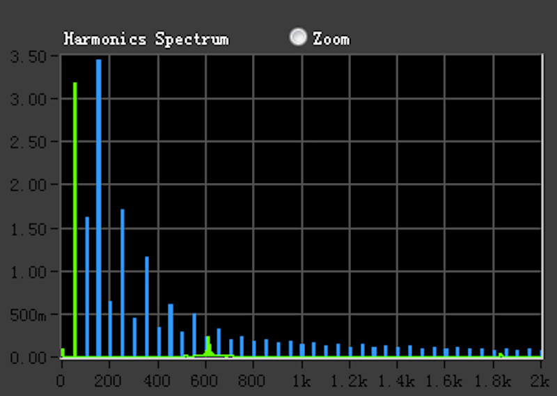
When selecting bar chart the actual measurements are shown (green) and the limits of the standard are shown (blue).
5. Definition of the window function
It may be selected Blackman-Harris, Hanning or Hamming or defined in the standard.
Presentation of the measurement results
The results of the harmonic currents are shown both as a table and as a graph. The table shows the numbers of harmonics (odd / even /all), the standard stored limit values (h (Arms /%)), the measured value of the corresponding harmonics (Meas (Arms /%)) and the PASS/FAIL evaluation listed. In addition, the total harmonic distortion (THD) is still displayed (up to the 40th harmonic).
The graph (selection: bar graph) shows the current measured value and the limit of the corresponding type (A to D) is shown in the spectrum (see Figure 3). For a better and closer look it can also be zoomed in the graphical view.
Click image to enlarge
Figure 3: The graph shows the current measured value
Generating of a Test Report
After the measurements, all data and results can be exported or also an automatic test report can be generated. The software package UltraPower Analyzer together with the Rigol-Oscilloscopes DS/MSO2000/DS/MSO4000and DS6000 etc. and the corresponding probes, is a complete solution for measuring switching power supplies and do a first rough look insight regarding the performance of the standard limits of IEC61000-3-2.
The package is optimized for preliminary tests of switching power supplies during development. It is also aimed at manufacturers of electronic household, audio/video and communication products. For example, to measure the built-in switch mode power supplies (in-house development or externally bought) and for the determination of specification of the Parameter of the final product, such as Inrush-current or power-consumption.
Nowadays, even end customers of consumer electronics are beginning to question and critically analyze these parameters during the purchasing procedure. Therefore having well-prepared and complete data sheets could be an ideal tool for manufacturers to promote the product.
Similar to the EMC pre-compliance testing during the design phase, the costs for certification and the time to market can be reduced with a test solution such as Rigol’s.