Partial discharge testing can be used as a non-destructive and predictive analysis tool, which warns of potential impending system as well as identifying insulation faults
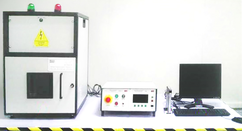
Figure 1: Test equipment for partial discharge testing with test chamber, partial discharge tester, and computer with measurement software
During their extensive service life, low-power transformers are subjected to a wide variety of stress. The electrical insulation, which is essential for fault-free operation, can be damaged as a result. Despite taking the utmost care, small defects, cavities, cracks, inclusions in the dielectric, or inhomogeneities in the electrical insulating materials may already occur during production. If the insulation is located between an electrode system with a voltage applied, the electric field can locally overstress the insulation at these weak points. This may lead to partial discharge. In contrast to full discharge – a frequently visible and audible breakdown – partial discharges are incomplete electrical breakdowns. They only occur in part of the insulation and are almost never noticed directly. However, over time they lead to increasing insulation damage, which may result in complete loss.
Diagnostic Methods for Quality Assurance
Dielectric diagnostic methods are essential for providing quality assurance and maintaining the operational reliability of power transformers. The most commonly used method for evaluating the integrity of insulation is a high-voltage or dielectric strength test (high-potential test, hi-pot test). In this case, a high voltage is applied to each side of the insulation and the leakage current is measured. This allows users to quickly identify whether the insulation is faulty. The disadvantage of high-voltage tests is that the voltage (or the resulting leakage current) can damage the insulation and thus negatively impact the component. In addition, a hi-pot test can only detect defects that are already present.
Partial discharge testing, on the other hand, is a non-destructive method for evaluating the insulation condition of electrical equipment. This reliable and very sensitive method effectively detects the slightest of weak points in the insulation system.
Partial discharges often occur long before a defect in the insulation becomes apparent. The measurements therefore support quality assessment of the sample as well as strategic decisions regarding timely repair or replacement of the transformer before the equipment fails.
How Partial Discharge Testing Works
Partial discharge tests examine the charge distribution within an insulated section during an ionization cycle and allow more accurate prediction of possible breakdowns. However, the signals that indicate partial discharge are relatively weak. For measurement, a defined voltage is applied to the insulated section. This also builds up across all the defects. Once the inception voltage Ui has been reached, the defect ionizes, thereby shorting itself out. When the voltage across the defect drops below the extinction voltage Ue, ionization ceases. During this process, the charge is redistributed within the insulated section. This is known as partial discharge. If the applied AC voltage is large enough, the partial discharge cycle is repeated many times. The partial discharge activity increases over time and can lead to irreversible damage to the insulation systems and eventually to dielectric breakdown.
The total charge redistributed within the insulated section is a very good indicator of the number of faults and the probability of a failure occurring. If the limit for the partial discharge test is set low, a high-voltage failure will most probably not occur during the entire service life of the component. Partial discharge testing is used to determine the maximum dielectric breakdown insulation capability of the component and the continuous insulation capability for a realistic usage scenario of the component.
The tests and test setups depend on the type of equipment being measured and the standard according to which the partial discharge measurement is to be performed.
Partial Discharge Testing
Pulse uses a procedure based on standards IEC 60664-1 and IEC 61800-5-1, which describe and specify a detailed process for performing partial discharge testing. According to IEC 60664-1, the partial discharge voltage needs to be sinusoidal during AC voltage tests for the continuous insulation capability of the component. However, if a constant DC insulation strength must be confirmed, an equivalent AC partial discharge voltage is used. The relationship between AC and DC voltage is defined as UPD = UDC/√2; where UDC is the constant DC insulation voltage and UPD the equivalent AC partial discharge voltage.
For a more stringent risk assessment, IEC 60664-1 prescribes different multiplication or safety factors. They include the environment correction multiplier (temperature, humidity), the hysteresis factor (difference between inception voltage Ui and extinction voltage Ue), and the safety factor. At Pulse, this results in an overall test value of 1.875·UPD for the partial discharge voltage.
The test equipment for partial discharge testing is shown in Fig. 1. It consists of a test chamber, the partial discharge tester, and a computer with the measurement software for displaying the measured values.
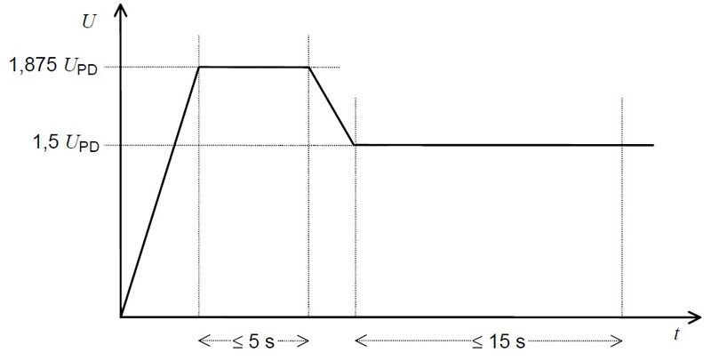
Testing starts with a voltage below the nominal partial discharge voltage UPD. This voltage is increased linearly to the test value of 1.875·UPD and held for a maximum of 5 seconds. The voltage is then reduced linearly to 1.5·UPD and held for a maximum of 15 seconds. During this time, the partial discharge is measured. Fig. 2 shows the voltage curve over time.
Click image to enlarge
Figure 2: Voltage curve over time during the partial discharge test
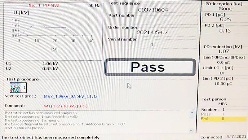
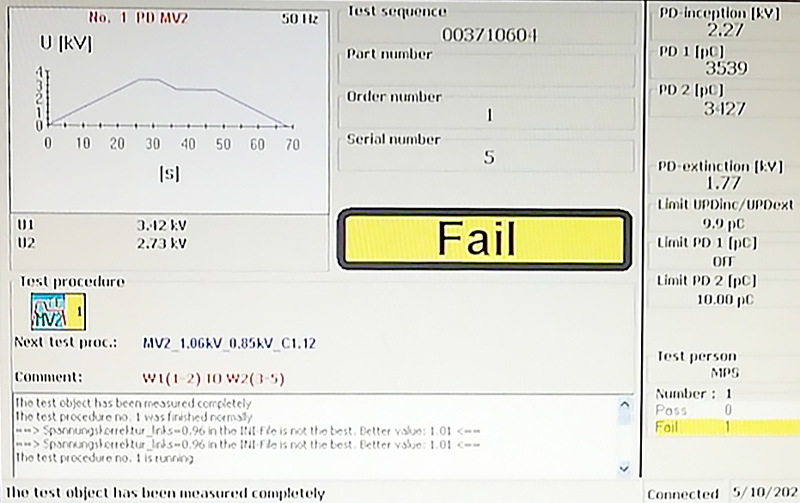
According to standards IEC 60664-1 and IEC 61800-5-1, a transformer passes the partial discharge test if the charge of the stray capacitances is less than 10 pC during the measurement period.
Fig. 3 shows the measurement of the charge of the stray capacitances during the partial discharge test. In Fig. 3 on the left, the sample passes the partial discharge test because the stray capacitance charge is less than 10 pC during the test period (see measured value PD1 and PD2). The component shown in Fig. 3 on the right does not pass the partial discharge test because the stray capacitance charge is well above 10 pC during the measurement period.
Click image to enlarge
Figures 3a & 3b: Measurement results of two partial discharge tests
Partial Discharge Testing for Quality Assurance
Especially within the first few years of operation, insulation defects occur disproportionately. Therefore, Pulse performs a partial discharge test after production as a type and acceptance test to detect any quality problems that may have arisen during production.
This applies, for example, to the automotive-grade version of four popular push-pull transformer series from Pulse. These transformers in the IATF product portfolio are matched to several available push-pull driver ICs (Fig. 4) and deliver up to 3 W of power with insulations ranging from functional to reinforced and up to 5.5 kVrms galvanic isolation.

Click image to enlarge
Figure 4: Push-pull transformers
The PH90/PM21 series also includes Pulse’s patented Sidecar package, which achieves a creepage distance of up to 12 mm in a compact SMD footprint.
These AEC-Q200-qualified transformers are used in communication, BMS, and IGBT drive applications, such as electric and hybrid vehicles.
The PH9185NL series (Fig. 5) is also tested for fatigue strength. The high-insulation switched-mode power supply unit transformers provide reinforced insulation for RS-485 and RS-232 transceiver ICs. The UPD of the partial discharge test is 1,000 Vrms; therefore, the fatigue strength (continuous) is also specified as 1,000 Vrms.

Click image to enlarge
Figure 5: Push-pull transformer with reinforced insulation for separate power supply drivers, 8 mm creepage distance, 5 kVrms insulation (1,000 Vrms continuous)
Summary
Partial discharge testing is an excellent way to identify critical insulation weaknesses in a magnetic component. It indicates potential long-term problems and can also be used to establish a maximum continuous voltage rating. It is recommended to perform partial discharge measurements and analyses not only to confirm operational safety after production but also after commissioning and – depending on the type of equipment – throughout its entire service life.


