The Basics & Benefits of Tantalum & Ceramic Capacitors
A comparative selection guide
Tantalum (Ta) capacitors and multilayer ceramic capacitors (MLCCs) are two widely accepted capacitor technologies that can be employed in a wide range of electronics applications. Although both technologies perform the same basic function, they are very different in terms of their construction techniques, materials, and performance under various conditions, so it’s important to understand the potential impact of selecting one over the other. Understanding the inherent characteristics of both tantalum capacitors and MLCCs, including their reliability and behavior with temperature and voltage, typical testing capabilities, and the latest developments for each will help ensure sound selections.
Capacitor Basics
The basic formula for capacitance is C = εr * ε0 * (A/d), in which
· C = capacitance, in Farads (F)
· A = the area of overlap between the two plates in square meters (m2)
· εr = relative static permittivity or the dielectric constant
· ε0 = the electric constant (ε0 ≈ 8.854×10⁻¹²F/m)
· d = the separation between the plates in meters or, essentially, the dielectric thickness.
Tantalum Capacitors
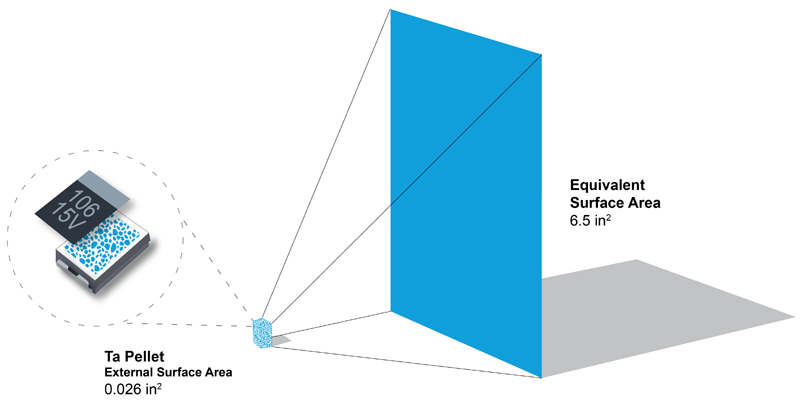
Tantalum capacitors achieve high capacitance values through a combination of factors, including a tantalum pentoxide (Ta2O5, εr = 27) dielectric, a large plate area (A), and a very thin dielectric thickness (d). The positively charged dielectric plate of a tantalum capacitor is formed from pure elemental grade tantalum powder that is pressed and sintered into a pellet. These pellets are extremely porous and, as such, allow the surface area of each individual particle to collectively comprise the area of an equivalent capacitor plate. In addition, the Ta2O5 dielectric layer is formed at a rate of 17 Ångströms per volt, with the thickness proportional to the applied voltage, which results in a very thin dielectric layer and contributes to large capacitance values.
Tantalum Capacitor Styles
For surface-mount applications, AVX manufactures two styles of tantalum capacitors, both of which incorporate an MnO2-based cathode to take advantage of its self-healing characteristics and are shown in Figure 2. The molded style (top) is the more traditional configuration and utilizes a tantalum wire embedded in the pellet to create the positive connection to the circuit. The newer, smaller, microchip-style configuration (bottom) was introduced to market more recently and is used in applications with high component density and minimal available board space. The microchip-style configuration has a tantalum wafer with tantalum powder pressed and sintered onto its surface and defines individual anodes using a high precision sawing operation. Both types of capacitors have the same basic elements and both have been proven suitable for the highest reliability applications over decades of production and testing.

Click image to enlarge
Figure 2a & 2b: A molded tantalum capacitor (top) and a microchip-style tantalum capacitor (bottom)
Ceramic Capacitors
In contrast to tantalum capacitors, ceramic capacitors have less overall plate area and significantly thicker layers, but compensate for such deficiencies by using dielectric materials with a much higher dielectric constant. Titanium dioxide (εr ~ 86–173) and barium titanate (εr ~ 1250–10000) are two of the most popular dielectric materials used to make MLCCs, and each material comprises its own class of capacitors.
Click image to enlarge
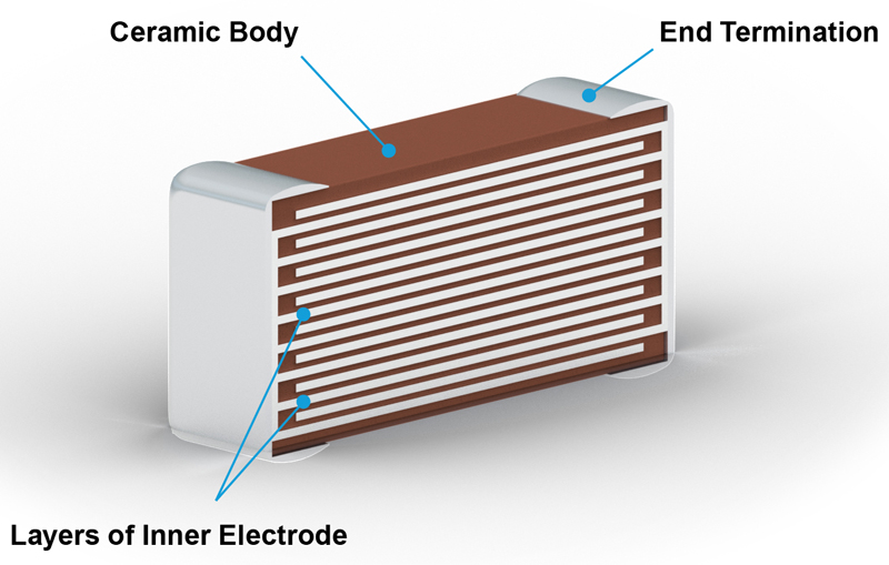
Figure 3: A multilayer ceramic capacitor
Class 1 and Class 2 Ceramic Capacitors
Class 1 ceramic capacitors offer the most stable capacitance with respect to applied voltage, temperature and, to some extent, frequency. The basic elements of Class 1 ceramic capacitors are composed of paraelectric materials, such as titanium dioxide, that are modified by additives including zinc, zirconium, and niobium in order to achieve the desired linear capacitance characteristics that are inherent to tantalum. Class 1 ceramic capacitors also have the lowest volumetric efficiency among ceramic capacitors due to the relatively low permittivity (εr ~ 6–200) of the paraelectric materials used and, as such, offer capacitance values in the lower range.
Class 2 ceramic capacitors utilize ferroelectric dielectric materials, such as barium titanate (BaTiO), and are modified by additives including aluminum silicate, magnesium silicate, and aluminium oxide. These materials have a higher permittivity than Class 1 capacitors (εr ~ 200–14,000 depending on field strength) and achieve better volumetric efficiency, but exhibit lower accuracy and stability. Class 2 capacitors also have nonlinear capacitance values that are dependent on both operating temperatures and applied voltage and will age over time, which can affect performance.
Ceramic Capacitor Dielectric Codes
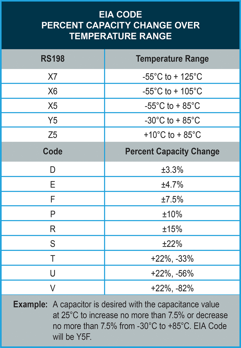
Ceramic capacitor dielectrics are defined by a three-character EIA code that specifies the material’s capacitance stability over a specified temperature range. For instance, ceramic capacitors made using X5R dielectric materials have an operating temperature range of -55°C to +85°C with an allowable variation in capacitance of ±15% over that range and exhibit non-linear capacitance value stability over that range.
Similarly, any material that allows a device to meet or exceed the X7R temperature characteristics, ±15% capacitance variation over a temperature range of -55°C to +125°C, can be called X7R. There are no voltage coefficient specifications for X7R or any other type of dielectric. A vendor can call a capacitor X7R, X5R, or any other of dielectric code as long as it meets the temperature coefficient specifications, regardless of how bad the voltage coefficient is.
Click image to enlarge
Figure 4: EIA code table for ceramic capacitor dielectrics
Tantalum vs. Ceramic Capacitor Performance
Tantalum vs. Ceramic Capacitor Temperature Response
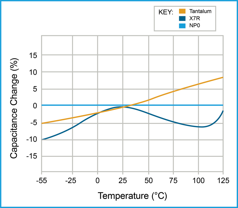
Figure 5 illustrates the typical capacitance response over temperature for tantalum capacitors, Class 2 ceramic (X7R) capacitors, and Class 1 ceramic (NP0 or C0G) capacitors. The tantalum capacitor exhibits linear capacitance change with respect to temperature: -5% capacitance change at -55°C to 8+% at 125°C. Class 2 ceramic capacitors demonstrate the most non-linear response to temperature, but can be made to achieve similarly desirable linear performance in applications with narrow operating temperature ranges (e.g., medical implantable devices) by accounting for the temperature response when designing the circuit.
Click image to enlarge
Figure 5: Capacitance change over temperature for tantalum, Class 1 ceramic, and Class 2 ceramic dielectric materials
Tantalum vs. Ceramic Capacitor Voltage Response
In addition to providing linear performance over temperature, tantalum capacitors do not demonstrate capacitance instability with respect to applied voltage. Unlike tantalum capacitors, the capacitance of Class 2 ceramic capacitors changes with applied voltage because the permittivity of the dielectric shrinks in response to higher applied voltages. These changes are relatively linear and thus easy to account for in circuit designs, but some higher permittivity dielectrics can lose as much as 70% or more of their initial capacitance when operated at or near rated voltage.

Click image to enlarge
Figure 6: Capacitance change over voltage for a Class 2 (X5R) ceramic capacitor
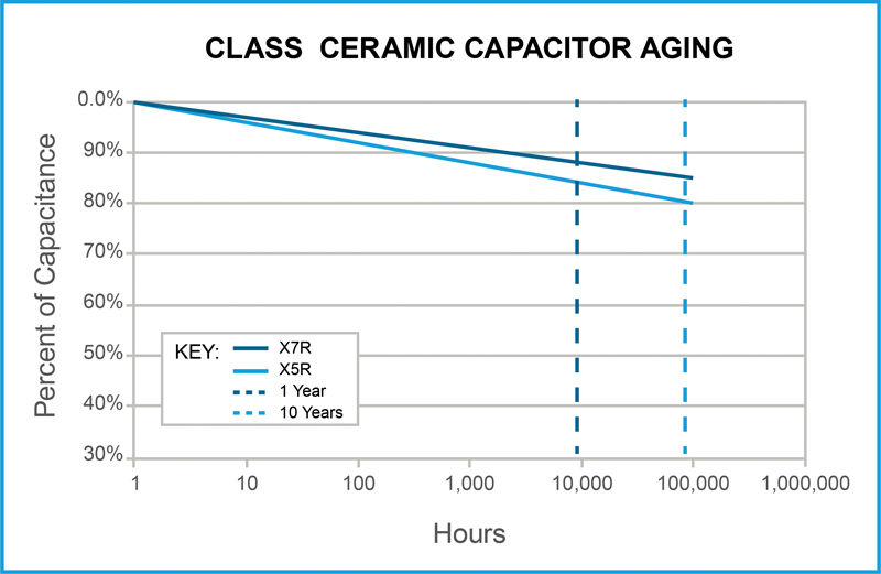
Tantalum vs. Ceramic Capacitor Aging
Class 2 ceramic capacitors also exhibit a logarithmic decrease in capacitance over time, which is referred to as aging. Degradation of the polarized domains in these ferroelectric dielectrics decreases permittivity over time, causing the capacitance of Class 2 ceramic capacitors to decrease as the component ages. Tantalum capacitors do not experience similar aging and have no known wear-out mechanism.
Click image to enlarge
Figure 7: Capacitance change over time for Class 2 X7R and X5R dielectric capacitors
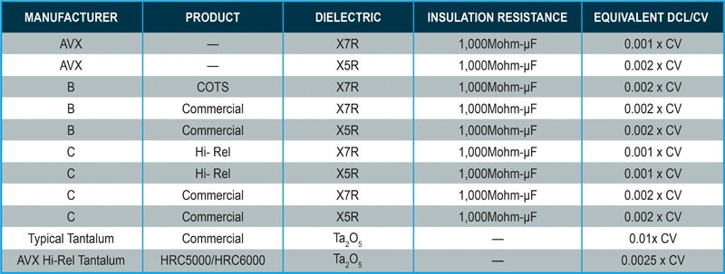
Tantalum vs. Ceramic Capacitor IR and DCL
Insulation resistance is the resistance measured across the dielectric of a capacitor. As capacitance values (and hence the area of dielectric) increases, the IR decreases. So, the product (C x IR or RC) is often specified in Ohm Farads or, more commonly, megaohms. Leakage current is determined by dividing the rated voltage by IR (per Ohm’s Law). Ceramic capacitors typically specify insulation resistance, whereas tantalum capacitors are graded by direct current leakage (or DCL). These units are equivalent and conversion from one measure to the other is made using Ohm’s law.
Click image to enlarge
Figure 8: A comparison of the IR of ceramic capacitors to DCL of tantalum capacitors
Tantalum vs. Ceramic Capacitor Testing
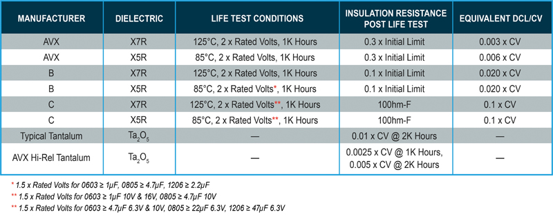
Tantalum vs. Ceramic Capacitor IR Life Test
Figure 9 depicts the life test conditions for various types of ceramic and tantalum capacitors made by several different manufacturers and the allowable change in insulation resistance and/or DCL/CV. As shown, the conditions for life testing are not standardized, so direct comparisons between ceramic capacitors made by various manufacturers are difficult to make with a high degree of certainty and direct comparisons from ceramic to tantalum capacitors is virtually impossible, save for the exception of a few very high capacitance ratings.
Click image to enlarge
Figure 9: Life test variation between ceramic and tantalum capacitors
Due to the notable differences between most of the test methods used to evaluate tantalum and ceramic capacitors, a direct comparison of their relative performance isn’t easily obtained via product literature and specification data. As such, AVX conducted the following testing to provide a more direct comparison of their respective performance.
Tantalum vs. Ceramic Comparative Testing
The AVX team selected samples of ceramic and tantalum capacitors that represent common ratings for both technologies and commonly used values for medical and other high-reliability applications.
• Tantalum Capacitor (TBCR106K016CRLB5000)
o 10μF, 16V
o 0805 case size
• Ceramic Capacitor (MQ05YD106KGT1AN)
o 10μF, 16V
o 0805 case size
o X5R dielectric
The team submitted all parts to the same test plan to ensure that special testing requirements (e.g., capacitance test frequency and DC Bias, hold times after environmental testing, etc.) could be accurately observed, collected, and compared for both basic product types.
• Temperature Stability (MIL-PRF-55365) – 13 units
• Thermal Shock (MIL-STD-202 Method 107) – 40 units
• Moisture Resistance (MIL-STD-202 Method 106) – 40 units
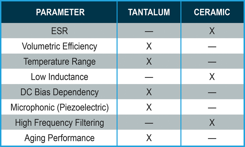
A majority of the test results showed similar performance between the ceramic and tantalum capacitors. For example, temperature stability showed that ceramic capacitors are more stable with regard to equivalent series resistance (ESR) and DCL, while tantalum capacitors are more stable for capacitance value over temperature. Tantalum capacitors also exhibited a capacitance increase at elevated temperature, while ceramic capacitors exhibited capacitance decreases at the same condition. In addition, both moisture resistance and thermal shock testing resulting in stable performance for both technologies.
Click image to enlarge
Figure 10: A comparison of tantalum and ceramic capacitor parameters
In conclusion, both tantalum and ceramic capacitors offer several advantages and benefits that aid in the manufacturing of efficient, high-reliability electronics across a wide range of markets. However, since both capacitors differ significantly with regard to their composition, materials, and performance, the choice between specifying one technology over the other comes down to specific application considerations and requirements. So, it is important for engineers to take the potential effects of component selection into account early on in their design phase.
AVX Corporation


