The Dawn of a New Era with High-Power Wireless Charging
Key features, benefits, and application examples of Infineon’s highly integrated WLC1115 wireless charging controller
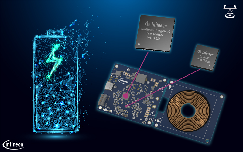
Figure 1: Wireless power transmitter system with WLC1115
Overview of Inductive charging and Qi specification
Wireless charging technologies range from inductive, magnetic resonant, and capacitive to RF radiation, laser, acoustic, and other emerging ones. The inductive coupling technology is the front runner [1], and hence its associated standard Qi is the most prevalent in wireless charging.
Inductive charging works based on Faraday’s law, where an alternating current in the Power Transmitter (PTx) coil(s) generates an alternating magnetic field. This magnetic field is then mutually coupled to the Power Receiver (PRx) coil and transformed back into an alternating electrical current rectified for the DC load connected on the receiver side.
The Wireless Power Consortium (WPC) manages the respective specification release for this technology. Currently, at version 1.3.2, the new release of Qi specification clearly demonstrates the intent for safe, high power (>5 W) wireless charging by adopting features such as enhanced Foreign Object Detection (FOD), transmitter authentication with private key storage, and protocol features for better interoperability. The Baseline Power Profile (BPP) of Qi specification limits the maximum delivered power to 5 W, while the Extended Power Profile (EPP) supports a power transfer up to 15 W.
Yet, in the era of powerful smartphones with fast wired charging over a USB-C interface, the user experience of charging speed using Qi wireless power transfer is still evolving, paving the way for new solutions. This article introduces Infineon’s first-generation wireless charging controller that integrates the latest Qi transmitter, USB-PD/PPS sink, DC/DC controller, gate drivers, sensing/protection peripherals, and configurable flash memory. Our programmable solution offers higher levels of flexibility along with the integration benefits, enabling designers to scale higher power levels and allow OEMs to offer differentiated features while remaining Qi-compatible.
Proprietary Power Extensions with Qi backward compatibility
While the war of standards may be over for inductive wireless charging, OEMs still have a continuous wish for differentiated features and enhanced user experience. This has led to the emergence of Proprietary Fast Charging protocols that coexist with the Qi standard.
The WPC protocol provisions for Proprietary Power Delivery Extensions (PPDEs) enable manufacturers to extend their solutions’ capabilities. Further, several smartphone OEMs offer proprietary high-power inductive wireless charging up to 50 W, limited by the regional spectrum regulations. As the Qi standard continues to evolve and may offer fast charging with increased power capability in the future, the product manufacturers look for flexible, programmable solutions that can be software upgraded, maintained, and offer enhanced user experience over the product lifetime.
Key features of WLC1115 transmitter controller IC
Integrated buck and inverter power stage
Infineon’s WLC1115 transmitter controller IC is a highly integrated, Qi-compliant wireless transmitter with integrated USB Type-C power delivery (PD). It complies with the latest Qi and USB-C PD specifications and has integrated gate drivers for buck and inverter power stage MOSFETs. It also includes hardware-controlled protection features.
The WLC1115 uses the integrated buck controller to generate the required bridge voltage to power the full-bridge inverter, which, in turn, supplies the Power Transmitter (PTx) LC tank to deliver power to the Power Receiver (PRx). The buck converter supports an input voltage range of 4.5 V to 24 V.
The integrated gate drivers of the WLC1115 are designed to control a full-bridge or half-bridge inverter depending on the Qi specification type and the operating scenario. The MP-A11 coil-based transmitter system shown in Figure 1 uses the fixed-frequency variable-input voltage control for the inverter stage.
Using WLC1115 in such a transmitter offers the following benefits to the power stage:
1. Highly integrated PD-based solution, compliant with latest USB Type-C PD requirements
2. Integrated gate drivers and firmware-configurable turn-on/-off gate drive strength
3. Programmable switching frequency range up to 600 kHz
4. Flexibility to dynamically change input voltage from 5 V to 20 V with PD input
a. This helps to achieve good efficiency with a USB-PD type input. For instance, the input voltage can be dynamically configured to keep the buck stage input close to the output, optimizing the buck stage efficiency. Peak 15 W efficiency measured from 15 V PTx input to 12 V PRx output is greater than 83 percent [3].
b. Reduces standby power by operating at 5 V in idle mode. This is typically about 67 mW [3] and can be further reduced below 25 mW with system-specific firmware enhancements.
5. Protections on the input- and output side of the buck stage:
a. Input UVP, OVP,
b. Output UVP, OVP,
c. Output OCP, SCP,
d. Protections specific to PD (e.g., VBUS to CC short)
Communication and Authentication
The Qi EPP standard requires bi-directional in-band communication. The communication from PTx to PRx is based on a Frequency Shift Keying (FSK) scheme implemented by the PTx, alternating the carrier wave frequency. The communication from PRx to PTx is based on an Amplitude Shift Keying (ASK) scheme created by modulating the load on the PRx side, causing a reflection to appear on the PTx, which is filtered and decoded.
The WLC1115 transmitter controller, being on the PTx side, implements the ASK demodulation and decoding scheme by detecting voltage and current variations in the PTx coil. In FSK, the PTx changes its operating frequency from the current to an alternate frequency to encode information.
The Qi 1.3.x specification mandates authentication for EPP Power Delivery of more than 5 W. It follows the public key cryptography that relies on a public and private key pair to encrypt and decrypt the content. These keys are mathematically related, and the content encrypted by one of the keys can be decrypted by using the other key. The private key is the most sensitive secure credential and must be stored securely. The public key is typically a part of the binary certificate, and this certificate is transmitted to the recipient through the in-band communication medium.
According to the Qi specification, the PTx must securely host the product unit’s private key in a storage subsystem for digital signature purposes. This private key is used to digitally sign the Challenge Authentication response from the power transmitter device. Our solution uses the OPTIGA™ Trust Charge device for this private key storage (Figure 2) [5].
Click image to enlarge
Figure 2: Key controllers in Infineon’s companion REF kit
The companion REF kit, Wireless Charging MP A11 Power Transmitter REFWLCTX15WC1, using Infineon’s WLC1115 transmitter controller IC and OPTIGA™ Trust Charge IC authentication solution for wireless charging meets the requirements of Qi authentication.
Foreign Object Detection (FOD)
WLC1115 transmitter controller also supports enhanced foreign object detection (FOD) as per Qi v1.3.2 standard. This includes FOD based on Q factor, resonance frequency, power loss, and over temperature (if a thermistor is used).
The Q factor and resonance frequency measurements are used for FOD before the power delivery phase. The PRx reports the Q factor and resonance frequency reference values calibrated with a Qi-defined reference coil. The PTx compares the reported values to its measured values in situ to determine the presence of a foreign object. A scaling factor is used to convert the PRx-reported Q factor and resonance frequency values to those equivalent to the reference transmitter coil and to accommodate measurement variations.
The power loss method is mainly used during the power transfer phase. The power loss FOD uses the PTx power measured at the buck output, which is fed to the inverter bridge. This PTx power is further adjusted by tuning FOD coefficients to account for inverter losses and friendly metal losses. After computing the calibrated PTx power, the result is compared against the latest PRx reported power value. A FOD event is logged if the difference between the calibrated PTx power and PRx power exceeds the Ploss threshold.
To prevent erroneous disconnects and improve user experience, WLC1115 uses an adaptive algorithm that distinguishes between real Ploss FOD vs. Ploss arising from poorly-coupled PRx. The FOD coefficients and the Ploss thresholds are fully configurable to adapt to the system design. As an example, Figure 3 shows the improvement in the active charging area with a PRx that has magnetic alignment aid as well as potential friendly metals.

Click image to enlarge
Figure 3: Adaptive foreign object detection (FOD) – A 74 percent improvement in the active charging area for Apple iPhone 12
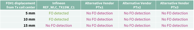
Another example (Table 1) shows the ability of our PTx with adaptive FOD algorithm to detect an object such as stainless steel, as defined by Qi specification [2] as FO1 while introduced during charging of a large phablet like a smartphone.
Click image to enlarge
Table 1: Large smartphone foreign object detection (FOD) – Ability to detect FO1 with Samsung Note 20 smartphone up to 10 mm
Programmability for proprietary extensions
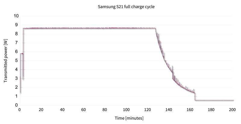
The companion reference board using WLC1115 wireless charging controller IC supports Samsung Proprietary Charging Extension. The software included provides Application Programming Interfaces (APIs) to the Stack Libraries that provide access to various functions that can be used to implement further such Proprietary Protocol Extensions over Qi. Shown in Figure 4 below is a Samsung phone consuming PTx power of about 9 W compared to BPP, which is only 5 W.
Click image to enlarge
Figure 4: Charge cycle result for Samsung Galaxy S21 smartphone (with Samsung proprietary extension)
Configurable software for various applications using WLC1115
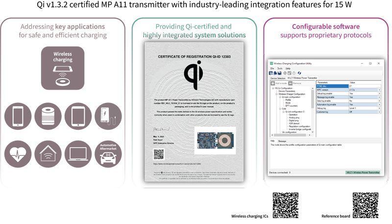
Infineon’s WLC1115 transmitter controller IC comes with a Qi v1.3.2 certified MP A11 power transmitter reference solution, targeting various applications, including smartphones, smart speakers, docking stations, monitor stands, as well as industrial or healthcare accessories (Figure 5).
Click image to enlarge
Figure 5: Qi v1.3.2 certified MP A11 transmitter with industry-leading integration features for 15 W maximum output power
In addition to the reference solution, WLC1115 is supported with a Configuration Utility available for downloading as well as Firmware Libraries via Infineon’s ModusToolbox™ software. The configuration utility is a Microsoft Windows application that guides the WLC1x user through the process of configuring and programming the chip. The utility works in tandem with the supplied hardware, which hosts the WLC1x controller IC together with a USB interface. The Graphical User Interface (GUI) allows users to intuitively select and configure the application parameters. Some of these parameters, such as FOD tuning, are also further explained in the application notes [6]. In addition to wireless charging parameters, the utility also offers parameters that enable configuring the USB-PD input and protections (e.g., OVP, OCP, and OTP).
For example, by following a simple configuration procedure detailed in an Infineon’s Developer Community Knowledge Base Article [7], the REF solution can enable DC input power-based wireless charging operation. This fits well with applications that have fixed voltage rails, such as industrial robots, docking stations, and aftermarket accessories. The flexibility through Software Configuration offers a high degree of freedom to the end-product designer, from concept through mass production stages.
Conclusion
The past few years have seen very rapid development in the components and applications of smart charging technologies. While a great deal of focus has been on standardizing wired charging towards USB-C [8] to enable universal connectors, there is also a growing trend on making charging more pervasive and convenient for various user groups – this is the prime mover for wireless charging.
Our wireless charging solutions with integrated USB-C PD, combined with Infineon’s OPTIGA™ Trust Charge Authentication, offer a compelling BOM value proposition to OEMs looking to develop Qi v1.3.2 compliant transmitters. The key features, such as adaptive FOD, support for proprietary protocols, DC/DC controller integration, and software libraries, make our platform unique and well-positioned to cater to proprietary as well as emerging Qi standards for inductive wireless charging.
Please visit our Wireless Charging ICs website to explore how Infineon’s WLC programmable solutions are able to offer the required flexibility to scale to higher power levels while remaining Qi-compatible.
Power & Sensing Selection Guide 2022 | Speed up your component search. Download now.
References
[1] Sánchez et al., “Technical Supporting Study to Assess The status of Wireless Charging, ” European Commission, Fraunhofer IZM, 2021-09-07
[2] Wireless Power Consortium Qi Specification
[3] Infineon Technologies, “WLC1115 15-W MP-A11 wireless power transmitter reference board (REF_WLC_TX15W_C1) test report,” User Guide, 002-35395 Rev. A, 2022-05-25
[4] Smith, Kedilaya, “Hardware design guidelines for WLC transmitter,” Application Note, AN235387, 2022-05-12.
[5] Ramanujam, “Provisioning OPTIGA™ Trust Charge for WLC transmitters,” Application Note, AN235196, 2022-05-02
[6] Ramanujam, Chelluri, “Foreign object detection tuning guide for wireless power transmitters,” Application Note, AN234970, 2022-05-03.
[7] Infineon Technologies, “Enabling DC input power-based wireless charging operation on the REF_WLC_TX15W_C1 reference board,” Knowledge Base Article, KBA235366
[8] European Commission, “Proposal for a Directive amending Directive 2014/53/EU on the harmonization of the laws of the Member States relating to the making available on the market of radio equipment,” Online Document, 2021-09-23