The Evolution of Low Voltage Power Distribution in Automotive Electronics – From ICE to MHEV to BEV
Automotive electronics have gone through several eras of evolution in the past 30 years
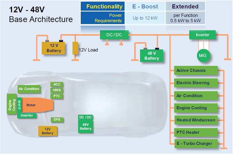
Figure 1: A typical dual-bus electrical system in a mild hybrid has the addition of a bi-directional DC-DC converter to allow power to flow between the two voltages when needed
Automotive electronics have gone through several eras of evolution in the past 30 years. The first stage was with pure internal combustion engines (ICE) that had mostly mechanical, or engine-driven systems such as power steering and air conditioning. The second stage – mild hybrid (MHEV) – was with the addition of electrical motivation; first in the form of start-stop function, followed by a rapid increase in the electrical drive to increase the electric/gasoline energy ratio and thus improve fuel efficiency.
In this second era of mild hybrid many of the functions that were driven mechanically were forced to transition to electric so they could continue to function when the ICE was stopped to preserve fuel during the start-stop function. In addition, cars were evolving with ever more powerful infotainment systems, cruise controls, suspension improvements, and safety features – all of which required increased electrical power.
In the third era, the fully battery-electric vehicle (BEV) has taken center stage. In addition to the traction drive to supply all the kinetic energy for motion, all functions must now be continuously powered by electricity.
In each of these three eras, the architecture, and even the basic semiconductor components for converting and distributing electrical power changed. This article discusses this evolution and makes some speculations about likely further evolutionary directions.
First Stage: Internal Combustion Engines (ICE)
The past was so much simpler from an electrical distribution point of view.
Internal combustion engines throughout the 1990’s and into the 2000’s consumed less than 1 kW of continuous electrical power, with about 12 kW required instantaneously to start the vehicle. A direct connection between the battery and the starter motor supplied the instantaneous power needed to start the vehicle. In addition, a belt-mounted alternator was used to supply continuous electrical power for loads such as the electronic ignition, engine management systems, audio system, and electric power windows.
Second Stage: Mild-Hybrid Electric Vehicles (MHEV)
Starting in the late 1990’s, cars with an electric motor that could start the engine as well as move the car forward a small distance until the ICE engine would take over began to reach consumers. In some cases, the electric motor was only used to start the engine that was shut down when the vehicle stopped, but in cases like the Honda Insight and the Toyota Prius, the electric motor could actually add to the power delivered by the ICE. As the technology evolved, more and more of the kinetic energy to move the car could be delivered by the electric motor, both boosting the overall power delivery of the system, and increasing the fuel economy of the vehicle. Electrical power requirements for the car saw a significant jump – ten times – from 3 kW for a simple start-stop system to 30 kW for a more advanced plug-in hybrid car.
No longer could the 12 V battery be used to supply simply an instantaneous boost to start the engine, now a larger source of regulated electricity had to become available. Initially, the increased size and capability of the starter – alternator, combined with a larger lead-acid battery was enough to handle the extra load. As the requirements grew from 3 kW towards the 10 kW needed for a mild-hybrid drive that delivers the bigger improvement in fuel economy, the load currents distributed throughout the vehicle climbed. Power had to be delivered to many more functions, including not only the electric drive, but also to the air conditioner, the fuel and water pumps, the power steering, and the infotainment systems.
At 3 kW, 12 V electrical wiring harnesses had to be able to handle 250 A. At 10 kW, this requirement jumped to 830 A. Electrical harnesses capable of this much current are expensive, heavy and difficult to rout throughout the vehicle. These increased electrical load demands were the primary motivation for the shift to 48 V as a voltage for distributing the electricity to the larger loads in hybrid vehicles.
The 48 V electrical distribution system was a logical choice as the peak voltages could be contained below the 60 V safety limit and it fell within available battery voltage, yet the nominal voltage of 48 V would reduce wire diameter used in the wiring harness to ¼ the size of a 12 V system.
The electrical architecture, however, became more complicated. Most of the automotive accessories use 12 V, so a fast transition from 12 V to 48 V is not possible. Instead, dual systems need to be placed in service until all, or most electrical loads evolve to the higher voltage. Certainly, the larger loads such as the traction drive, and possibly the air conditioning and power steering, derive the largest benefits from the higher voltage wiring harness and have, or will soon transition.
Figure 1 shows a typical dual 12 V – 48 V system. There is an addition of a DC-DC converter between the 12 V and 48 V systems. This DC-DC converter needs to be bi-directional and able to convert 12 V to 48 V, or 48 V to 12 V. Additionally, the converter must be able to supply the maximum load required for the vehicle.
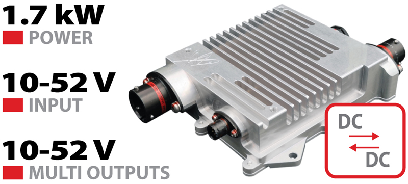
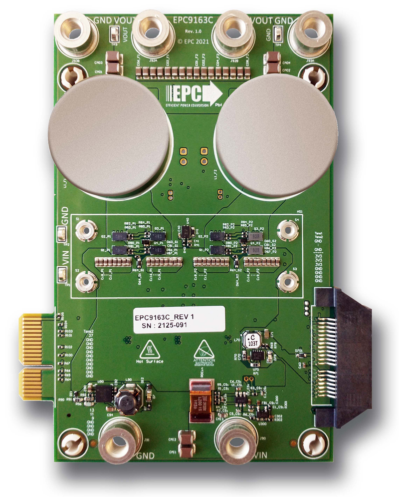
Figure 2 shows one DC-DC converter for automotive applications in production, and figure 3 shows a 2 kW system (EPC9163 demo system) without the housing and heatsink. Both examples use gallium nitride (GaN) transistors instead of the less attractive Si-based power MOSFETs due to GaN’s smaller size, higher conversion efficiency, and lower cost. The EPC9163 can be paralleled to deliver up to 10 kW.
Click image to enlarge
Figure 2: 1.7 kW automotive bi-directional GaN-based DC-DC converter manufactured by Brightloop
Click image to enlarge
Figure 3: EPC9163 demo system is a 2 kW bi-directional DC-DC converter featuring EPC2218 GaN transistors
Why GaN?
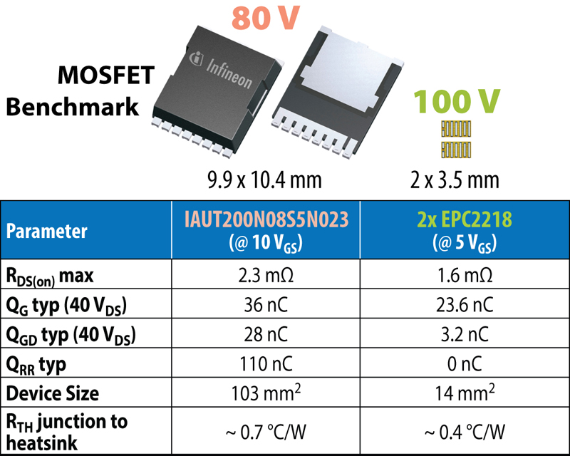
GaN transistors are rapidly displacing silicon MOSFETs in new applications in the 48 V range due to their superior performance and lower cost. Figure 4 is a comparison between a benchmark Si MOSFET and the GaN device used in the previously mentioned EPC9163. Note that the switching charge, QGD, is an order of magnitude lower than the equivalent MOSFET. This lower charge enables the DC-DC converter to operate at much higher frequencies, in this case 500 kHz versus a maximum of 125 kHz for MOSFET-based converters. Higher frequencies mean smaller inductors, fewer components overall, and higher efficiency.
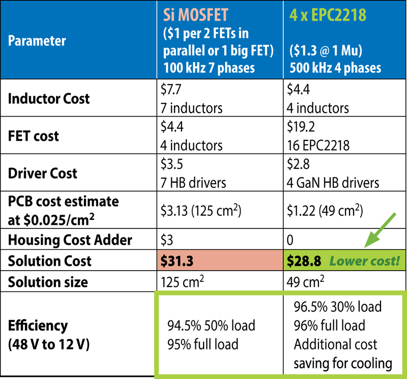
In figure 5, an estimate of the relative system costs of a 4 kW bi-directional 48 V – 12 V DC-DC converter using GaN transistors is compared with a converter using Si MOSFETs. In addition to the smaller size and lower cost, the overall GaN-based system is smaller and wastes 30% less power (96.5% vs. 94.5% efficiency). In some systems this difference in efficiency is the difference between requiring liquid cooling or a less-expensive air cooling approach.
Click image to enlarge
Figure 4: Comparison of key electrical and thermal characteristics between a benchmark Si MOSFET and the GaN devices used in the EPC9163
Click image to enlarge
Figure 5: Estimated relative system costs and conversion efficiency of a 4 kW bi-directional 48 V – 12 V DC-DC converter using GaN transistors compared with Si MOSFETs
GaN technology is still in its early stage of maturity compared with silicon. This maturity gap means that GaN technology will continue to evolve faster than the fully mature Si devices. Continued improvements in device performance and cost are realized every year. In addition, GaN devices in their 13 years of mass production have documented reliability and demonstrated robustness well beyond silicon’s capabilities.
Third Stage: Battery Electric Vehicles (BEV)
With the rapid adoption of battery electric vehicles comes new challenges for electrical distribution. The power requirements for the electrical loads are similar to those in a MHEV without the electric supplemental drive motor, but with the additional requirement for electrical heating and battery temperature management. This BEV electrical load is in the range of 3 kW. Wiring costs and power conversion efficiency requirements cause BEVs to benefit from the 48 V distribution system. One additional requirement is that the electrical bus, whether it be 12 V or 48 V (or both), needs to be charged from the same charging system as the main batteries. Electric vehicles today have traction drives that are mostly either 400 V or 800 V.
The auxiliary system, whether it is 48 V, 12 V, or both, therefore needs to be electrically isolated from the high voltage system to stay under the 60 V safety limits. The simplest solution is to add an 800 V/400 V to 48 V or 12 V isolated power supply. Common topologies are the CLLC or Phase-shifted full-bridge topologies. The primary side of the converter will either use silicon carbide (SiC) transistors, or GaN transistors. On the 48 V secondary side – the part of the circuit that is isolated from the high voltage primary side of the converter – GaN-based power conversion devices are the most efficient, smallest, and most cost-effective.
Lessons from Hi-Density Artificial Intelligence (AI) Servers
AI has received much publicity lately as public demonstrations from systems such as ChatGPT are approaching human-like characteristics and capabilities. Behind these incredible capabilities are massive numbers of high-performance servers using graphic processing units (GPUs) that are extremely power-hungry.
Over the past five years there has been a shift from power being centralized in a server rack to a distributed power architecture that converts from 408 V at the input of the rack to 48 V at the output. This replaces the previous standard of 12 V supplied to the server board from the rack. 48 V is then distributed from the rack onto the server board and converted to 12 V (or lower) in close proximity to each of the power-hungry GPUs. This distributed power architecture is more efficient due to lower losses in the distribution wiring.
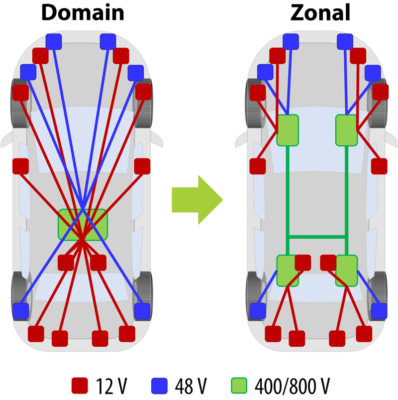
Automotive power distribution can also benefit from a distributed power architecture. By locating smaller 400 V/800 V DC-DC converters in defined zones around the vehicle, a simpler and more efficient wiring system is the result (see figure 6).
Click image to enlarge
Figure 6: Distributed power architecture (zonal) can reduce wiring harness costs and losses
Future Simplifications
As battery and traction technologies mature, many opportunities will emerge for saving costs and improving efficiency as well as performance. One example that seems likely is the elimination of the low voltage batteries altogether. This would save considerable weight and cost. Instead of bulky 12 V or 48 V batteries, the electrical loads could be serviced directly via the main battery system via smaller 400 V/ 800 V – 48 V isolated power supplies located near the load itself as in the zonal architecture of figure 6. Distributed architectures also provide opportunity for improved fault tolerance if designs include the ability to cross-supply power when needed.
Summary
The evolution of the car from ICE to BEV has significant implications for the architecture of the vehicles’ electrical systems. The move from 12 V to 48 V is being driven by cost and efficiency requirements in MHEV vehicles that have increasing electrical power loads.
In BEVs, the ancillary electrical load is less than the MHEV because the traction drive is driven from a separate system. Nevertheless, the increased electrical loads in modern BEVs greatly favor the adoption of 48 V electrical distribution buses. BEVs, however, have the additional requirement of an isolated DC-DC conversion from the main battery bank (400 V – 800 V) to the accessory voltages of 48 V and 12 V. GaN power devices are playing a significant role in this transition due to their smaller size, higher conversion efficiency, and lower cost compared with the aging silicon ancestors.
.jpeg)