The Growing Ecosystem for eGaN FET Power Conversion
Rapid progress continues in the development of faster, better, and smaller eGaN FETs
In recent years, GaN-based power conversion has increased in popularity due to the inherent benefits of eGaN FETs over conventional Si transistors. Migrating a converter design from Si to GaN offers many system-level improvements, which require consideration of all the components in that system. This trend has subsequently spurred a growth in the ecosystem of power electronics components that support GaN-based designs.
An eGaN FET power conversion system offers the benefits of higher efficiency, power density, and lower overall system cost than Si based alternatives. This drives the need for a comprehensive ecosystem of gate drivers, controllers, and passive components that support these advanced systems. In the past several years, there has been a surge in the market availability of these components, with specifications well-suited to eGaN FETs, and many designed specifically to support a GaN-based conversion system.
Overview of an eGaN FET Power Conversion System
The characteristics of eGaN FETs have begun to change the power converter landscape, allowing higher frequency operation and higher density configurations than their slower, bulkier Si predecessors. Examples of emerging GaN-based converters are 6.78 MHz wireless power amplifiers, envelope tracking power supplies, time-of-flight lidar systems, and high frequency DC to DC converters. Each of these applications have unique characteristics and design requirements for the supporting components, but the majority of these requirements apply to general GaN-based power conversion.
One popular converter is the synchronous buck converter, which will be used as the basis for further high-level discussion of the eGaN ecosystem. Some specific requirements for other applications will subsequently be mentioned as well.
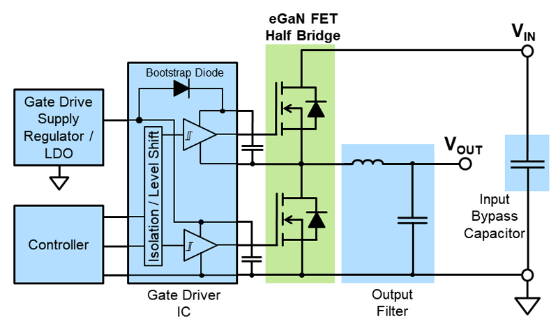
Figure 1 shows a typical synchronous buck converter with the building blocks that make up the surrounding system. These building blocks include a gate driver with signal isolation or level shifting, a controller, bypass capacitors, and output filter inductors. The requirements for these building blocks are driven in part by the characteristics of eGaN FETs, namely: small footprint, fast switching, tight gate voltage requirement, and high frequency capability. Each building block must meet certain requirements to effectively support an eGaN FET power conversion system.
The expanding eGaN FET ecosystem is broken down into three main categories: gate driver ICs, controllers, and passive components. These components must reliably support the eGaN FET and enhance its performance. They must also offer a cost-effective solution and be easy to incorporate into the design.
Gate Driver ICs for eGaN FETs
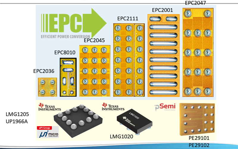
The gate driver IC is the most critical supporting component for an eGaN FET based converter. Some examples of gate drivers suitable for eGaN FETs are shown in Figure 2. These ICs must be capable of operating at higher frequencies than traditional MOSFET drivers, while exposed to much higher slew rates. In addition, they must meet the tight gate voltage requirements of eGaN FETs while providing the necessary drive strength to achieve fast turn-on and turn-off speeds. Drive strength is characterized by the source/sink resistances and peak currents, coupled with the rise and fall times of the driver’s output voltage.
In a half-bridge circuit, such as the one depicted in Figure 1, the gate driver for the high-side device is referenced to the switch node, which experiences a high slew rate during switching transitions. The high-side driver is therefore isolated from ground using either a level shifter or a signal isolator. The isolation barrier must be capable of withstanding the high voltage slew rate at the switch node, which typically exceeds 50 V/ns for an eGaN FET, and often reaches well above 100 V/ns. This capability is characterized by common-mode transient immunity (CMTI). If the voltage slew rate at the switch-node exceeds the CMTI, this isolation barrier may break down and cause spurious switching events to occur.
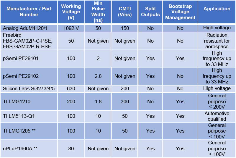
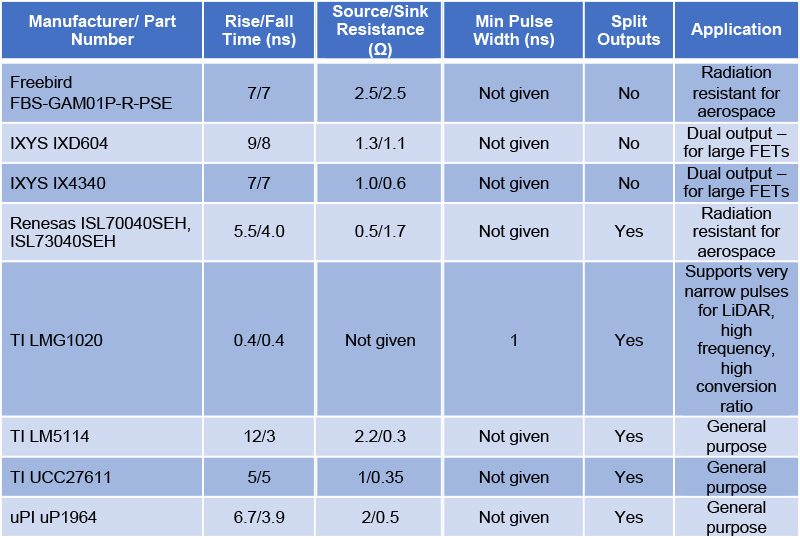
A half-bridge driver includes an isolator or level-shifter within the same IC package, and it can therefore drive both the high-side and low-side FETs in a half-bridge topology. Table 1 lists some of the half-bridge gate drivers compatible with eGaN FETs. Gate drivers have recently become available with CMTI of 200 V/ns or higher, such as LMG1210 from Texas Instruments and Si827x from Silicon Labs. Table 2 lists non-isolated gate drivers that are suitable for eGaN FETs in applications other than half-bridge topologies. These drivers can also be used to drive high-side devices by pairing with discrete isolators, such as ADuM1xx and ADuM2xx from Analog Devices, Si86xxxT from Silicon Labs, and ISO7821F from Texas Instruments.
Click image to enlarge
Figure 2: Examples of gate driver options, shown to relative scale with eGaN FETs
Click image to enlarge
Table 1: Half-bridge and high-side gate driver ICs for eGaN FETs.
** Footprint compatible
Click image to enlarge
Table 2: Non-isolated gate driver ICs for eGaN FETs.
To effectively drive eGaN FETs, the gate driver must meet or exceed the following key parameters:
· UVLO compatibility with the 5 V gate requirement of eGaN FETs
· A low parasitic package and footprint that ensures maximum performance in the layout
· Sufficiently high drive strength: rise and fall times typically < 10 ns, source and sink resistances typically < 2 Ω, peak source/sink currents typically > 1 A
· Minimum CMTI > 50 V/ns, or even higher as required for some eGaN FETs and applications
· Low propagation delay mismatch/skew, typically < 10 ns, which is crucial for minimizing dead time and ensuring control stability at high frequency
· Low minimum pulse width, particularly important for high conversion ratio and dual edge triggered Lidar applications
Other value-added features for eGaN drivers include
· Split pull-up/pull-down outputs for asymmetric gate resistance adjustment, which is particularly important for devices with higher miller ratios
· An integrated bootstrap diode with zero or very low reverse recovery charge and well capacitance, which is critical for high voltage and high frequency applications
· Bootstrap voltage regulation or active clamping to prevent high side gate over-voltage
· Shoot-through protection and/or dead time management
· Integrated de-glitching for enhanced noise immunity
· Radiation resistance for aerospace applications
Recently, eGaN gate drivers have begun moving towards direct footprint compatibility between different vendors. One such example is the Texas Instruments’ LMG1205 and uPI Semiconductor’s uP1966A gate drivers. This opens the door to second sourcing and design flexibility for the customer.
Controllers
As eGaN FETs push converters to higher frequencies, controllers are required that can operate in the MHz range. There is a subsequent expectation for higher control bandwidth and tighter regulation for high-frequency converters that imposes additional requirements on the controller. Other controller functions impacted by eGaN FET characteristics include the feedback amplifier, dead time management, and short-circuit protection. Many controllers also incorporate a gate driver stage, which must meet the same gate driver requirements previously mentioned.
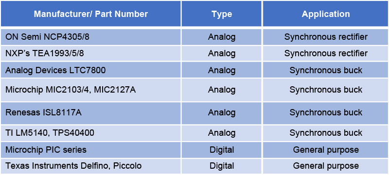
Each analog controller is designed for a particular range of applications. For example, Table 3 lists some eGaN compatible controllers for synchronous rectifier and synchronous buck applications.
Key added-value features for analog controllers include
· Current sensing and feedback control
· Adaptive dead time management for minimizing reverse conduction loss
· Pulse skipping or burst mode (for improved light load operation)
· Over-current/short-circuit protection
Digital controllers are also useful for many eGaN applications, such as multi-phase and multi-level architectures. Digital signal processors (DSPs) for eGaN must have sufficient clock frequency and processing power, while also providing enough analog/PWM outputs and digital I/O’s to support the desired control functions. Suitable examples include Microchip’s PIC series and TI’s Delfino and Piccolo series.
Click image to enlarge
Table 3: Suitable controllers for eGaN FETs.
Passive Components
The higher operating frequency of GaN based converters means that passive components must be optimized for higher frequencies. The two types of passive components that have experienced advancements in support of GaN converters are inductors and capacitors.
A key metric in a GaN converter performance is power density, which includes the input and output filter. The passive filter components are often the largest and highest loss elements in a system. This often becomes the limiting factor on the high power density of the eGaN FET power stage. Achieving high power density and efficiency requires a small inductor with high frequency and current capability. Important inductor parameters include low series resistance (ESR) to minimize conduction loss, low core loss, and low parasitic capacitance. One example of a suitable output inductor for a GaN-based converter is Vishay’s IHLP series, which is used in eGaN FET demonstration boards EPC9204, EPC9205, and several wireless power converters.
Appropriate capacitor selection is also important, particularly for the bypass/decoupling capacitors across a half bridge. The ultra-fast switching speed of an eGaN FET causes very high current slew rates (did/dt), and the power loop inductance must be minimized to limit voltage spikes (Lloop Ïdid/dt). Minimizing Lloop relies heavily on the bypass capacitor bank, which must provide sufficient capacitance and voltage rating to support the switching transient, while also maintaining a small footprint and a low parasitic inductance (ESL). Suitable ceramic capacitors that meet these criteria are available from multiple vendors to support eGaN designs. Typical examples include 0402, 0603, or 0805 footprints, with temperature coefficients of X7R or X7S.
Example eGaN FET Power Conversion System: The EPC9130 Development Board
The growing GaN ecosystem provides a wealth of options for the eGaN FETs, gate drivers, isolators, controllers, and passives. When appropriately selected, these components work together to contribute to the overall system-level advantage over conventional Si alternatives. These benefits are most clearly expressed in terms of power density and efficiency.
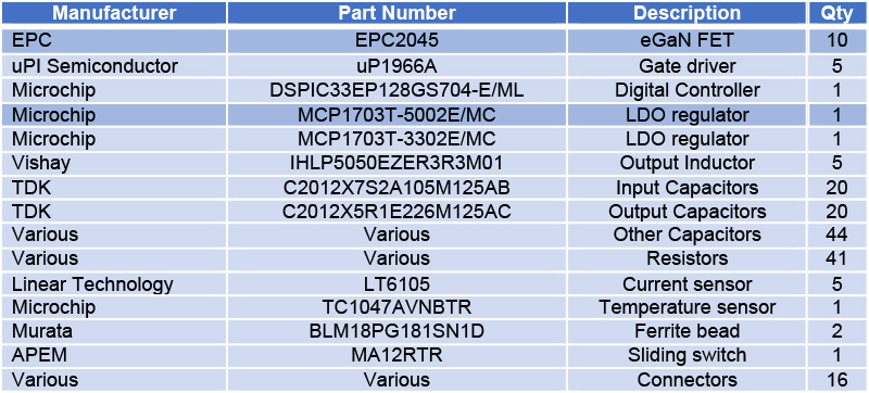
An excellent example is the five-phase synchronous buck converter development board EPC9130, pictured in Figure 3. This 48 V to 12 V converter includes five identical eGaN power stages configured in parallel, controlled by a single DSP that manages current sharing with closed-loop voltage regulation. The EPC9130 achieves an astounding power density of >1000 W/in3, efficiency > 96%, and a bill of materials cost of only 6 cents per Watt. The five-phase design makes this converter easily scalable to meet a wide range of system requirements.
Key components in this design include the EPC2045 GeN5 eGaN FETs, uPI Semiconductor’s uP1966A half-bridge gate drivers, Vishay IHLP series inductors, TDK ceramic capacitors, and Microchip PIC digital controller. Figure 3 depicts the EPC9130 development board with each of these components highlighted, and Table 4 lists its Bill of Materials (BOM).

Click image to enlarge
Figure 3: EPC9130, 48 V to 12 V 5-phase regulated IBC using EPC2045 eGaN FETs.
Click image to enlarge
Table 4: Bill of Materials for EPC9130 Development Board.
Conclusion
As eGaN FETs continue to become smaller and faster, the surrounding ecosystem of supporting components is increasingly critical to widespread adoption. This ecosystem is no longer a limiting factor in GaN-based designs, and customers have a rapidly growing number of options. Going to GaN has never been easier or more effective, and this progress continues at an unprecedented rate.
EPC (Efficient Power Conversion)


