New inductors are more powerful and efficient than ever. Combine a fundamental understanding of their specifications with the latest tools to unlock their full potential
Traditionally, off-the-shelf power inductors have offered the capability to perform a variety of functions and serve many different applications. The same inductor might have served one circuit as a ripple-smoothing element in an LC output filter and as an EMI suppression choke in another.
By contrast, a device like a DC-DC controller IC has typically been used only for its originally intended purpose. Such a device might be adjustable or programmable for different frequencies, load ranges, or converter modes, but it is safe to say that it is usually used to control a dc-dc converter.
Today, despite the fact that more and more inductors are designed with features optimized to improve performance in very specific circuits, inductors do remain quite versatile and are almost always useful in multiple applications. This means there is great opportunity for you to select from an entire catalog of off-the-shelf parts to find an inductor that is perfect for your purpose, avoiding the need to create a custom design or search endlessly for an inductor specifically labelled for that purpose, greatly reducing the time and cost of your design cycle.
Power Inductors Serve Multiple Applications
Semiconductor companies are very good at supplying sophisticated resources and “cookbooks” for their products. To help users, IC companies can provide very detailed reference designs that makes sense in the context of an intended application or set of related applications. In contrast, for fundamental elements like inductors, datasheets express more basic parameters that you can use to relate to a specific application. It seems counterintuitive, but the more complicated device can be easier to use thanks to step-by-step documentation for its intended application, whereas building block components place a different onus on the user to decide how best to use those components. This is both a challenge and an opportunity. Do not be put off or intimidated. Inductor datasheets have plenty of helpful information.
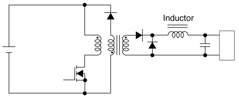
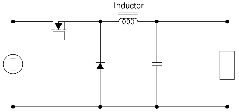
Consider a buck converter inductor versus the output inductor of a forward converter. In the forward converter, the inductor is part of the output L-C filter to smooth the ripple current. These might seem like different uses, but both functions simply require an inductive reactance to shape the current waveformby and do it with as little power loss as possible.
Click image to enlarge
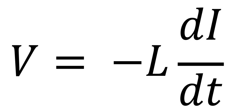
Equation 1
Click image to enlarge
Figure 1a: Forward converter here
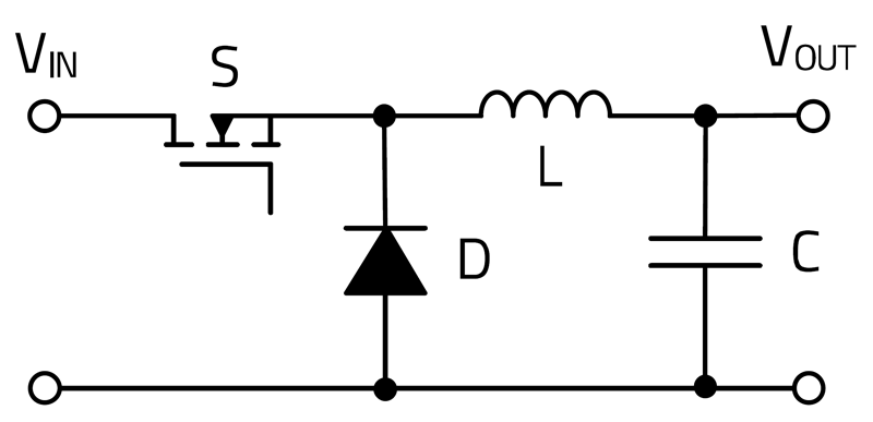
Click image to enlarge
Figure 1b: Buck converters
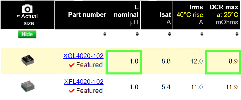
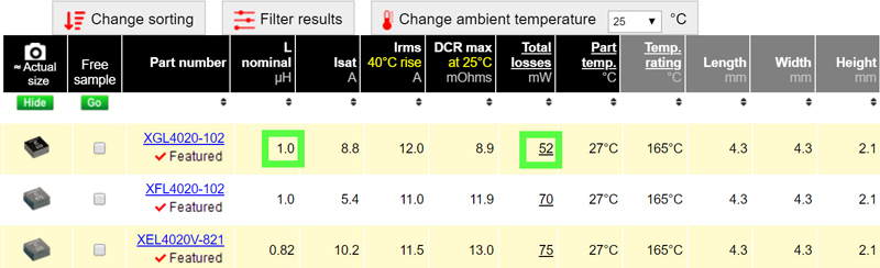
In the simplest case, this means selecting an inductor with the right value (L) and the smallest wire resistance (DCR) as shown in Figure 2.
Click image to enlarge
Figure 2:1 µH inductors sorted for the lowest DCR
It can be just that quick and easy to find a solution. However, as you might guess, going beyond just “getting the job done” to find the most optimal solution can be more complicated. You will want to consider the best tradeoffs between DCR and size, as well as current rating and size. In addition, experienced designers know they must also consider inductor saturation and AC losses. There are many parameters to consider for selecting the optimized power inductor, and abundant information is available to give you a full picture of how an inductor will operate in typical converter operation. An online comparison tool (as shown in Figure 3) readily provides all the necessary information, including datasheet parameters as well as active performance parameters specific to a user’s application (e.g., inductance at peak current and total losses and temperature rise). For example, if you are most interested in efficiency, you can now pick the inductor with the lowest total losses.
Click image to enlarge
Figure 3: 1 µH inductors showing parameters that are more pertinent
New Applications
With this abundance of information, power converter designers have a good toolbox available when looking for a “typical” continuous-conduction-mode power inductor with well-behaved ripple current. However, application and technology trends take us ever further from the “usual” applications. For example, “Wide Vin” requirements cause converters to work with new duty cycles and different waveforms than we might be used to. In addition, not all converters are straightforward continuous power devices (e.g., pulsed power to charge capacitors or drive transducers for ultrasound, radar or LiDAR). Other applications also need “power” inductors. For example, an inductor used as an EMI noise filter choke on a 5 A supply line must be rated for 5 A, of course, but should that be a different inductor than used in a 5 A buck converter? The good news is that inductor datasheets and tools have also evolved and are quite useful when answering these questions, whatever your application might be.
Creative Use of Datasheet Information
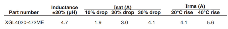
Inductors have current ratings related to continuous current, but some applications require an inductor that survives a very high current for a short duration of time. How can you use a standard inductor datasheet to find the best part for this application? Consider these specifications for the Coilcraft XGL4020-472, an industry leading, low-loss, off-the-shelf 4.7 µH power inductor:
Click image to enlarge
Figure 4: Off-the-shelf inductor specifications
This inductor is clearly well suited for continuous current of 3-4 A or more, but consider an application that subjects the inductor to a short term 10 A pulse during a short-circuit condition. At first glance 10 A appears to be quite a bit of current since it is approximately twice any of the published current “ratings.” However, a short-term pulse of 10 A is, in fact, no problem for this inductor. Inductor ratings for saturation current and heating current can show this.
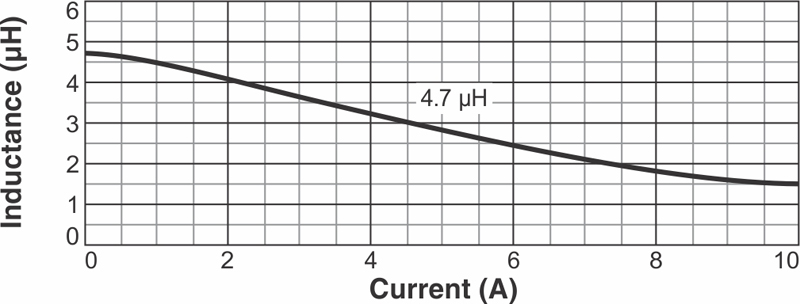
For saturation, a 10 A pulse will certainly drop the inductance below the nominal 4.7 uH (Figure 5), but saturation itself does no harm to the inductor and is a reversible process — when the short circuit condition is removed and the current drops, the inductance “recovers” to its original non-saturated value. As they say in basketball, “No harm, no foul.” The phenomenon of saturation does not permanently harm the inductor.
Click image to enlarge
Figure 5: Inductance vs. Current
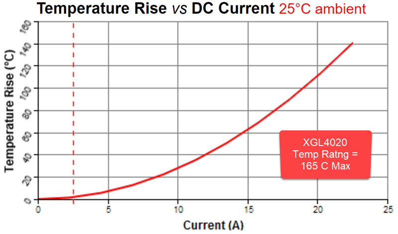
Excessive temperature, on the other hand, can cause damage to insulation. A closer look at the Irms (“heating current”) for this inductor shows the impact of 10 A through this inductor. Figure 6 shows 10 A will cause about 130°C temp rise in the inductor, which sounds like it might be too much until you consider the inductor is rated for 165°C. This means continuous current as high as 10 A would be fine for this inductor. So certainly, a short duration pulse of 10 A is perfectly acceptable as well. This demonstrates just one example of how inductors can be much more versatile and robust than portrayed by the limited numbers on a traditional datasheet. Irms current ratings have been shown in roughly the same form for many years. These numbers make it easy for you to compare one inductor against another, but they do not necessarily convey application-specific information.
It would be understandable for an inexperienced designer to see something called a current “rating” on an inductor datasheet and assume it is a maximum limit if careful attention is not paid to how the numbers are derived. Inductor current ratings of this kind should be used as informational guidance, not limits. Historically, you would need a certain level of expertise in inductor specifications, performance and design in order to go “beyond the datasheet.” Today, online tools and calculators that can consider user-specified application conditions and demonstrate inductor performance (as shown in Figure 3) serve you much better. Note the Ipeak, L@current, total losses, and inductor temperature shown are all based on user inputs.
Click image to enlarge
Figure 6:Temperature Rise vs. Current
Current ratings are fundamental inductor specifications that have been greatly enhanced by more complete datasheets and, especially, online tools. These tools give you the application-related information you need, without requiring you to become a magnetics expert.
Another fundamental consideration for inductors is performance related to frequency. Most datasheets have a nominal inductance value “as tested at” some default frequency like 100 kHz or 1 MHz. Very few converters switch at exactly one of these frequencies, so the most fundamental inductor characteristic may not provide complete guidance. It is important to remember that many “ratings” were never intended to replicate application conditions exactly, but rather were originally conceived to have a standardized way to compare inductors. Fortunately, there are resources available to understand frequency-dependent inductor operation at non-standard frequencies. First, datasheets do generally contain L vs F information and self-resonant frequency (SRF) is usually listed in the data table. Calculators like Coilcraft’s online Compare and Analyze tool provide efficiency or loss data at any given application frequency. And inductor models like SPICE circuit elements or s-parameters are readily available for those doing optimization analysis or wanting to avoid the time and expense of building prototypes.
Conclusion
Inductors are essential building blocks of electronic circuits, and they may be used in a variety of ways. Datasheets provide the fundamental parameters, but to take full advantage of these versatile components, it is necessary to use the data sheets and modern calculators in ways that are as creative as the circuit designs they serve.