Modeling an energy harvesting application using a TEM to generate electrical current in the presence of a temperature gradient.
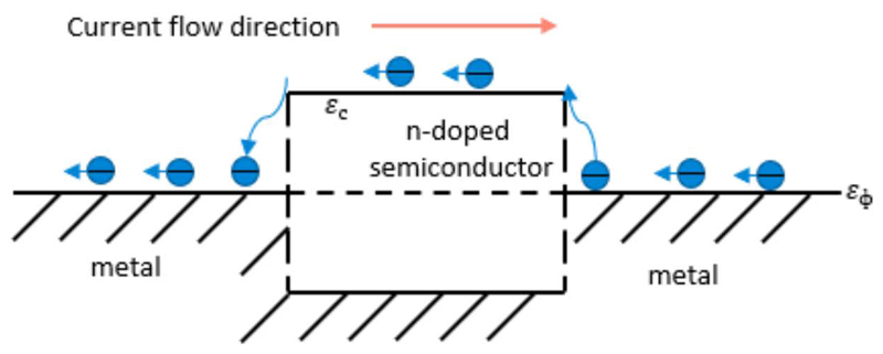
Figure 1: Cooling/heating effect at the conductors’ junctions during current flow (Peltier effect)
Some remote sensors are required to stay active in the field for a period longer than it’s possible for a suitably sized battery to last. In such cases, an energy harvesting system may be added to extend the operating lifetime. Available ambient energy sources can include kinetic energy present in vibrations, light, or thermal energy, which can be captured using a thermoelectric module (TEM). Modeling such an energy harvesting system in LTspice lets engineers accurately assess its performance and simplify its development.
TEM – Technical Features and Implementation
A TEM produces an electric current relative to the temperature gradient across the module by leveraging the Peltier-Seebeck-Thomson effect.
The Peltier effect can be clearly represented by the behavior of the metal/semiconductor junction (Figure 1). Since the average energy of charge carriers in different conductors is different and varies depending on the materials energy spectrum, concentration, and scattering, then during the transition from one conductor to another, the electrons either transfer energy to (heating) or take from the lattice (cooling).
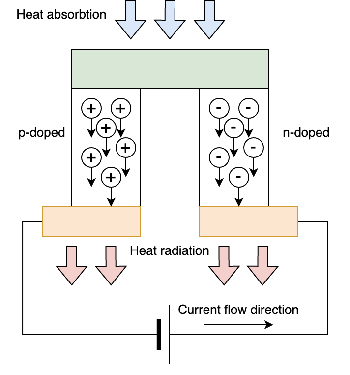
Modern TEMs are essentially thermocouples which contain p- and n-type semiconductor pillars electrically connected in series and thermally connected in parallel. (Figure 2)
Click image to enlarge
Figure 2: The structure of a semiconductor TEM
LTspice TEM Model
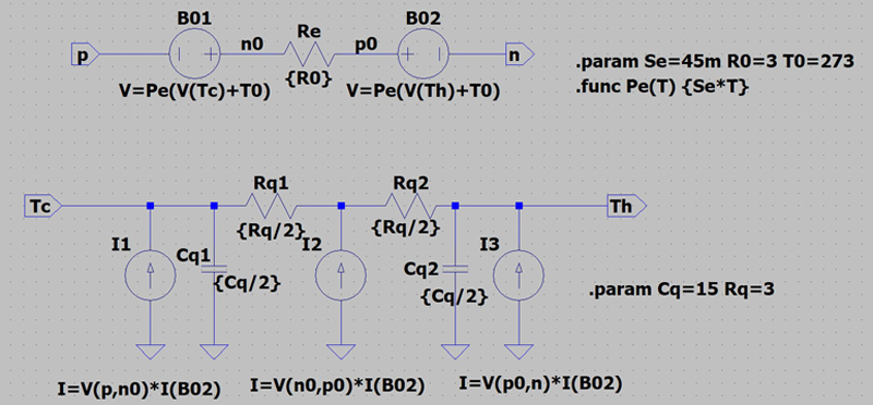
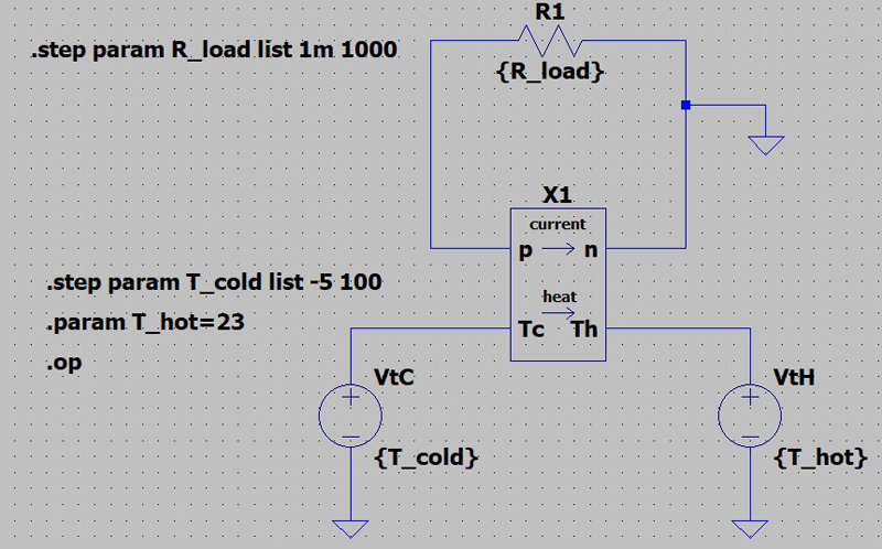
An LTspice model of a TEM is shown at Figure 3. This model consists of electrical and thermal sections, linked with each other by thermoelectrical voltage balance equation.
Click image to enlarge
Figure 3: TEM LTspice model
The electrical section of the model is determined by the Peltier-Seebeck-Thomson thermoelectrical effect. This effect describes a voltage, dependent on the junction temperature. To model this heat transfer, therefore, a behavioral voltage source was used. These voltage sources are dependent from the temperatures at the hot and cold sides of a TEM (Tc and Th respectively) multiplied by the parameter Se (Seebeck coefficient).
Click image to enlarge
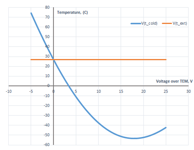
Figure 4: Calculation of temperature on the thermally un-stabilized TEM side, related to the voltage drop over the TEM (LTspice schematic and modeling result)
Parameter Calculations for Several Popular TEMs
To implement the Spice-model, a designer needs to convert the parameters of a TEM from its datasheets into a set of model parameters to program both the thermal and electrical sections of the system.
Manufacturers of TEMs normally provide the following parameters to specify their products:
● ΔTmax - the highest possible temperature difference between the hot and cold ceramic plates of a TEM for a fixed Th (temperature of the hot side)
● Imax - the input current to generate the maximum possible ΔT across a TEM
● Vmax - the dc voltage to generate the maximum possible ΔT at a supplied current I=Imax
● Qmax - the maximum amount of heat that can be absorbed at the TEM’s cold plate at an Imax and ΔT of 0
The practical formulae for calculating the set of Spice-model parameters are listed below:
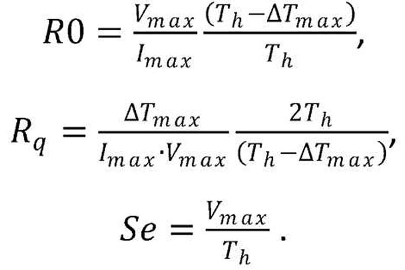
For simplicity, we assume that the thermal capacitance of ceramic plates is proportional to the square of the plates and the TEM’s body capacitance is proportional to the module’s volume.
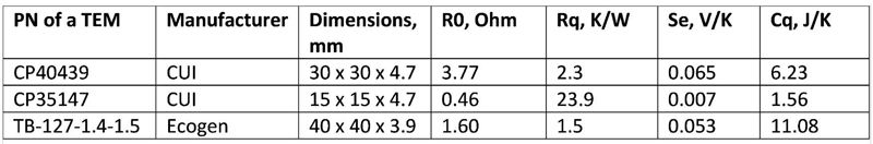
Table 1 presents the calculated parameters of several selected TEMs.
Click image to enlarge
Table 1: Calculated parameters for several TEM modules to be used in the SPICE simulation. [1,2,3]
Checking the Model for a Typical TEM
To check the behavior of the model, consider the parameters of CUI’s CP40439, a popular TEM, as shown in Table 1:
● Electrical: Se = 65 mV/K, R0 = 2.3 Ohm,
● Thermal: Сq = 6.23 J/K, Rq = 2.3 K/W.
The next step is to calculate the dependence of the temperature on the thermally un-stabilized side of the TEM from the voltage drop across the module. Sweeping the voltage drop in the range -5 V to +25 V distinctly shows the minimum temperature point observed on the TEM’s cold side at the value -52°C, (Fig. 4). If the voltage drop across the TEM is 0 V, the temperature on the cold side equals that on the hot side.
Let’s perform another calculation of the TEM’s performance with a load connected to electrical terminals. Assume two possible extreme states as follows: the first configuration with the load at 1 kOhm (this can show the performance in open-circuit state) and the second configuration with a very low resistance at 1 mOhm (this can show the performance in short-circuit state). Figure 5 shows the schematic of the test bench.
Click image to enlarge
Figure 5: LTspice system for a module’s extreme condition states (Short-circuit and open-circuit conditions)
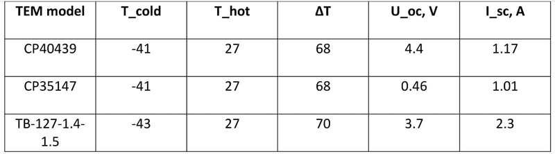
Table 2 summarizes the calculation results for different TEMs. The extreme conditions with temperature drop ΔT = T_hot – T_cold is set according to the respective supplier datasheets. These parameters can help to estimate the highest possible output values of a specific module.
Click image to enlarge
Table 2: Calculation results of various TEMs in open-circuit (OC) and short-circuit (SC) conditions at extreme temperature drops, specified by manufacturers. [1,2,3]
Practical Examples of LTspice Simulations
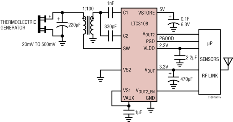
Analog Devices’ LTC3108 allows a designer to build a high-efficiency TEG. The main feature of this IC makes it possible to start energy harvesting when the input voltage from a Peltier element is as low as 20 mV. It delivers the obtained energy from the generator to a storage capacitor and an LDO output with a fixed voltage of 2.2V with up to 3 mA output capability. This controller also has a voltage output that can be programmed to a fixed value of either 2.35V, 3.3V, 4.1V, or 5V. Any of the voltage outputs are useful for powering a remote sensor MCU. To make the system even more robust, the LTC3108 has a Power-Good indicator that can show that the generator is within working conditions. Additionally, the system needs a compact step-up transformer with 1:25, 1:50 or 1:100 windings ratio.
The LTC3108 is a unipolar device that works only if one specific side of the TEM is the hot side. For applications where it is unknown which area will be warmer, it’s recommended to use the LTC3109, which can generate energy from any temperature gradient.
Click image to enlarge
Figure 6: The typical application schematic with LTC3108
The energy harvester with a LT3108 can be modeled in LTspice, using the standard model of LTC3108 and the TEM model, described in the previous sections. Bringing these two models together can help a designer assess the steady state and dynamic behaviors of the thermoelectric system. The calculation can show the performance of the energy harvesting for different temperature gradients for a variety of TEM models. The result of the modeling with a temperature gradient of 47°С shows that the system stabilizes to a steady state within 100 ms. The PGOOD flag goes high at Vout = 3.08 V, which is within the specified threshold 7.5% of programmed output voltage.
Modeling of a Temperature Stabilizer with LTM4663
Other types of TEM controllers from Analog Devices are available in the same µModule package type. One example is the LTM4663, which is an ultra-thin 1.5A µModule TEC regulator that sets, stabilizes, and monitors the cooler’s temperature. This device implements Analog’s patented current-stabilization scheme.
Current stabilization is provided by two stages of regulation: coarse, with the help of a PWM control circuit and fine, with the help of a linear power stage. This type of regulation permits high efficiency and small circuit size. The module temperature is monitored through the TSET input and compared with the thermistor value.
The temperature controllers with LTM4663 are actively used for temperature stabilization in optical communication systems, as well as medical and scientific devices.
By combining the TEM and LTM4663 models in LTspice, it is possible to calculate temperature-control scenarios feeding the voltage from the TEM model to the analog input TSET. With the known dynamic characteristics of the thermoelectric module, it is also possible to estimate the settling time on the side of the TEM with adjustable temperature.