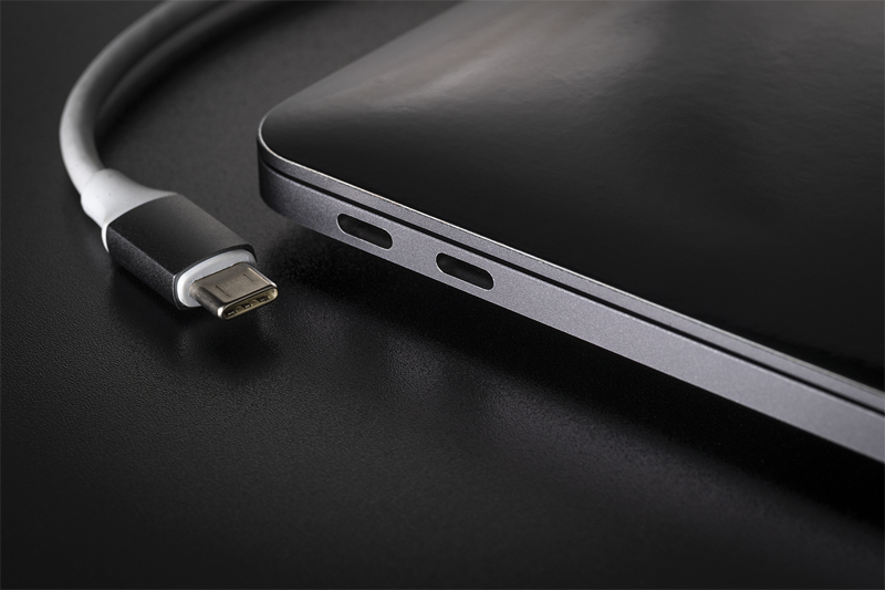
USB Type-C has simplified power delivery and connectivity, but as it is now often the only port available in systems, safe and reliable operation is paramount
Figure 1. USB-C Enables Compact, Slim Industrial Designs while Supporting Various
Power and Connectivity Standards
USB Type C adoption in notebooks, tablets, and smartphones continues to increase due to the features it offers. It is an upgrade to existing USB standards like USB 2.0 and 3.1 while also serving as a replacement for standards like Thunderbolt and Displayport. The smaller physical size of the connector has enabled slimmer laptops. At the same time, it is powerful enough to connect all the peripherals a user may want. From a user's point of view, the fact that the connector is reversible minimizes the number of times you have to flip the connector in an attempt to connect a peripheral. The multiple connectivity standards it supports to allow for physically large connectivity ports (USB Type A, AC adaptor barrel connectors, and ethernet CAT 5 cables) to be completely eliminated. Adopting Type C for power delivery and eliminating customized laptop adaptors and charging cables is also a green choice for manufacturers, as the purchase of a new laptop, tablet, or smartphone will not require the user to discard the power adaptor if it supports Type C.
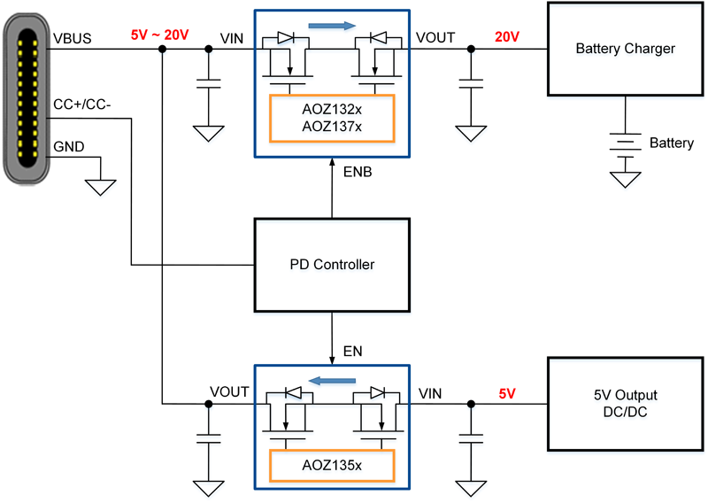
Type C Power Delivery Implementation in a Laptop
A typical laptop USB Type-D implementation is shown in Figure 2. The "sinking" power delivery path is to the laptop charger while the "sourcing" power path is from the laptop systems 5V rail. This is different from most type C implementations in a smartphone or tablet, which are typically single cells, and a buck-boost battery charger provides both sourcing and sinking paths.
Type-C "Sourcing" Switch Requirements
Laptops typically source a maximum of 5V/3A due to the implementation described above. It's unlikely that mainstream laptops will provide more than 15W to peripherals due to limitations in battery capacity. As such, the Type C sourcing switches do not pose a huge challenge for power MOSFET SOA. As power levels are low, a source to source resistance (RSSON) of about 30-35mOhm, such as that of the AOZ1356, is sufficient for the sourcing load switch function. Features such as overcurrent protection and short circuit protection are standard and protect the systems' 5V rail from overcurrent due to a shorted cable or malfunctioning load.
Click image to enlarge
Figure 2. Typical USB Type-C Power Delivery Implementation in a Laptop
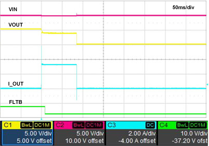
A more critical feature is reverse blocking, as manufacturers must protect against non-compliant or malfunctioning USB Type C adaptors. The USB Type-C specification requires that the adaptor outputs 5V and only after PD negotiation is allowed to ramp to the required voltage to power the system. A malfunctioning adaptor could provide this 20V directly. As all the Type C ports are connected to a common 5V system rail, protecting the system from such a fault is an important function that all Type C sourcing switches must provide. Figure 3 shows the reverse current protection (RCP) feature in AOZ1356LI in action.
Click image to enlarge
Figure 3. (From AOZ1356 Datasheet) Minimal Reverse current (<250mA) is allowed to flow as the load switch blocks reverse current due to 20V (abnormally applied while the AOZ1356 switch is on) on VOUT (Yellow trace). VIN (Internal 5V system rail in pink) shows minor perturbation of 100mV
Another key feature is "fast role swap" or FRS. FRS is a function that is extremely useful in preventing loss of data. Consider the case where a laptop may connect to a dock via its Type C port with several peripherals powered up through the dock's 5V USB Type C or USB Type A rails. In the event of power loss from the dock (either due to the dock power cable disconnected or loss of AC mains), the FRS function allows the laptop to very quickly (within 150µs) source 5V power any peripheral device that is connected to the dock and prevent data loss.
In order to do so, the 5V sourcing switch is turned on with minimum delay. USB Type C specifications require for this to happen within 150µs to prevent power loss to any USB peripheral powered by the dock's 5V rail. As the switch can only be enabled and disabled by the PD controller, this 150µs budget also includes the response time of the PD controller, which is typically 50µs. Therefore, the 5V sourcing load switch must have the ability to react in 100µs or less. Figure 4shows the AOZ1356 FRS function in action; a 60µs total response time ensures that the PD controller could take up to 90µs to respond to the FRS event, and the system would remain compliant to the USB Type C specification.

Click image to enlarge
Figure 4. AOZ1356LI FRS Operation: EN_to_Ramp_Delay = 20µs, Ramp Time = 40µs,
Total Delay = 60µs, I_IN peak = 2.1A
Type-C "Sinking" Switch Requirements
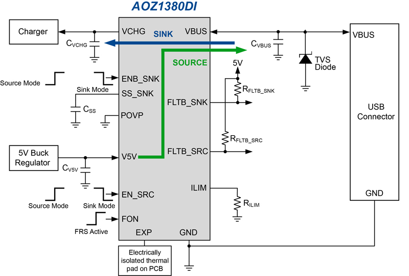
The sinking switch controls the voltage ramp and current transients during startup. It delivers constant current and intermittent pulsed current to the downstream system when the switch is fully on. Both the start-up and fully enhanced modes have unique challenges. In order to understand this, the AOZ1380, a combination sink and source Type C Protection switch will be used as an example of how these specific challenges are addressed. AOZ1380 takes advantage of co-packaging to integrate a discrete trench MOSFET with a controller designed on an IC process to enable the best of both worlds: the high SOA and low RDS(on) of a trench MOSFET with the ability to program soft-start, and offer a slew of protection features that is possible to design on an IC process.
Click image to enlarge
Figure 5. AOZ1380, Combination Sink and Source Load Switch
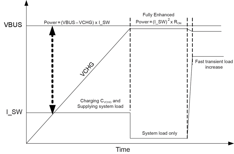
During start-up, the voltage at VCHG linearly ramps up to the VBUS voltage over a period of time set by the soft-start time. This ramp time is referred to as the soft-start time and is typically in milliseconds. Figure 6 illustrates the soft-start condition and power dissipation.
Click image to enlarge
Figure 6. Soft-Start Power Dissipation
During this soft-start time, there will be a large voltage across the power switch. Also, there will be current I_SWthrough the switch to charge the output capacitance. In addition, there may be load current to the downstream system as well. This total current is calculated as:
In the soft-start condition, the switch is operating in the linear mode, and power dissipation is high. The ability to handle this power is largely a function of the power MOSFET linear mode SOA and good package thermal performance (Rthj-c) as the soft-start ramp time is in milliseconds. Rthj-ambient, which is more a function of PCB thermal performance, doesn't play a role. With a high-reliability MOSFET as the power switch and superior packaging technology, the AOZ1380DI is capable of dissipating this power. The power dissipated is:

To calculate the average power dissipation during the soft-start period: ½ of the input voltage should be used as the output voltage will ramp towards the input voltage, as shown in Figure 6.
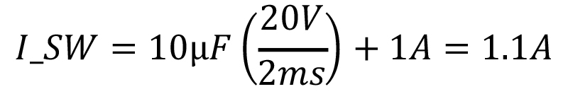
For example, if the output capacitance CVCHG is 10µF, the input voltage VBUS is 20V, the soft-start time is 2ms, and there is an additional 1A of system current (I_SYS), then the average powerbeing dissipated by the part is:

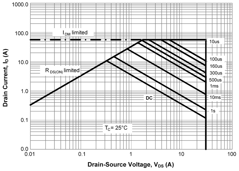
Referring to the SOA curve in Figure 7, the maximum power allowed for 2ms (DC) is 50W (2.5A x 20V or 5A x 10V). The AOZ1380DI power switch is robust enough to drive a large output capacitance with load in reasonable soft-start time.
Click image to enlarge
Figure 7. Safe Operating Area (SOA) Curves for Sink Power Switch
After soft-start is completed, the power switch is fully on, and it is at its lowest resistance. The power switch acts as a resistor. Under this condition, the power dissipation is much lower than the soft-start period. However, as this is a continuous current, a low on-resistance is required to minimize power dissipation. Attention must be paid to board layout so that losses dissipated in the sinking switch are dissipated to the PCB and hence the ambient. With a low on-resistance of 20mΩ, the AOZ1380DI provides the most efficient power delivery without much resistive power dissipation.
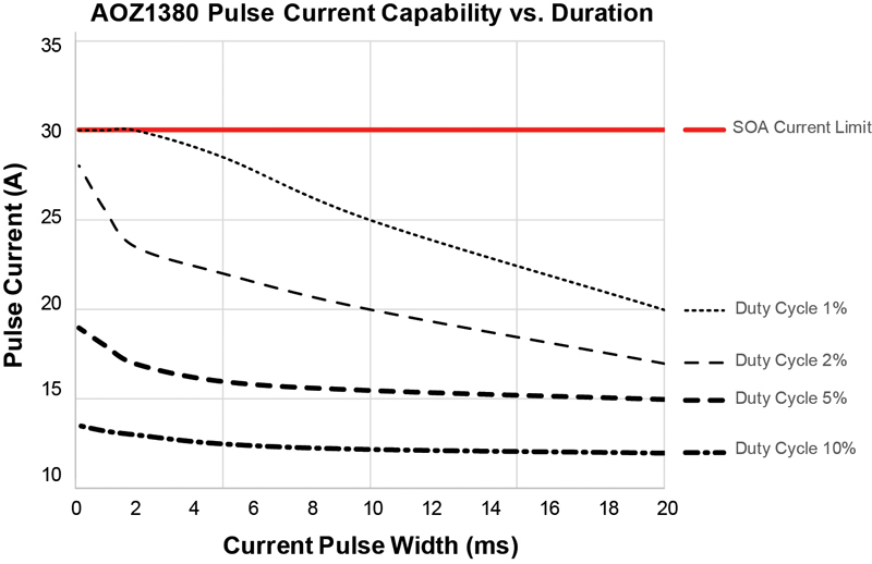
While Type C power delivery is limited to 20V @ 5Aor a 100W, many high-end laptops require peak currents far in excess of the 5A. While the thermal design current (TDC) for a CPU may be low, peak current (ICCmax in the case of Intel and EDP in the case of AMD) of many systemsis often 2 x thermal design current. These events are typical of short duration (<2ms) and low duty cycle, but they are important for system performance as a CPU/GPU capable of operating at several GHz can boost its compute power in those 2ms peak current events. The AOZ1380DI can handle such short, high current, transient pulses without any reliability degradation, thus enhancing the performance of high-end systems when plugged into the Type C adaptor.The shorter the pulse and the lower the duty cycle, the higher the pulse current that the part can sustain. The part has enough time to dissipate the heat generated from the pulse current with longer off-time, as shown in Figure 8. For example, AOZ1380DI can maintain 20A for 10ms with a duty cycle of 2%.
Click image to enlarge
Figure 8. AOZ1380 Sinking Switch Pulsed Current Magnitude vs. Duration for a given Duty Cycle
USB-C is quickly becoming the interface of choice as it supports multiple data and power standards. However, as manufacturers drop proprietary connectors, special care must be taken to protect the power path to avoid system damage as Type C must support both high voltage sinking path and a low voltage sourcing path. Exposing a low voltage 5V peripheral device, or for that matter, the internal 5V bus in the system to the 20V/5A (100W) capability of a Type C port can result in catastrophic damage. Features such as soft start, true reverse current blocking, and overvoltage protection are all essential features that must be provided by the power path switches. In addition, high SOA is required to support high power dissipation in a soft start as well as peak current events when system processors demand peak power.
While these functionalities can be implemented discretely, the solutions are cumbersome and occupy a large area. This would be counterproductive to compact industrial designs made possible by the slim and reversible Type C connector. Products like Alpha and Omega Semiconductor's Type C protection switches solve this by integrating these functions into a compact footprint. The AOZ1380, for example, provides both sourcing and sinking paths and simplifies the job of a system designer as he attempts to fit the functionality and features required of next-generation tablets, laptops, and PC peripherals while not compromising on the industrial design.