Achieving step-down conversion with a highly integrated module is now simpler and more efficient than ever before
Despite the development of ultralow power integrated devices, the overall demand for power at a system level is only increasing. At the same time, OEMs remain under pressure to make their end-applications physically smaller, which continues to drive demand for smaller and more efficient power supplies.
While improvements are constantly being made, power density remains a significant challenge for design engineers but one that has been successfully addressed using Point-of-Load (PoL) conversion; placing distributed and small step-down converters closer to the components that need them, thereby reducing the distribution losses and inefficiencies of large, centralized power conversion.
There are quite a few challenges in designing PoL converter systems for distributed power architectures. System boards are very space constrained, and not only must the power solution occupy minimal PCB real estate, it must also do so with a minimum of thermal and control issues. Efficiency is of critical importance to improve the throughput efficiency of the system, as well as to minimize temperature rise in components and ensure a long operational lifetime with a high degree of reliability and robustness.
The success of PoL has turned in to a trend, one that has continued to a point where a complete step-down DC/DC solution can now be achieved in a single package, using very few external components. As with every other aspect of power, efficiency is paramount, in both the execution and application. Developing step-down modules that meet designer’s requirements and expectations has led to the rapid growth of this area of engineering.
Constant on-time
A popular method for implementing step-down DC/DC conversion is an evolution of the simple hysteresis technique of alternately passing and blocking the output voltage based on its level. While simple, this method is inherently noisy from an electrical point of view, not least because the frequency with which the controller switches is unpredictable and variable.
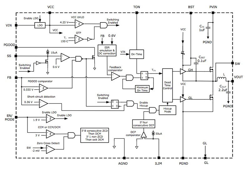
A synchronous step-down converter with a fixed switching frequency is, in essence, an extension of the hysteresis method but instead of a variable on-time, the on-time is constant. An example of an integrated step-down module is the XR79115 from Exar. Figure 1 shows a schematic representation of the device. It implements Exar’s proprietary emulated current-mode Constant On-Time (COT) technology, as implemented in a number of the company’s DC/DC converter modules, regulators and controllers. The technology successfully overcomes one of the challenges of using the COT method, that of reducing output ripple when using low-cost ceramic capacitors.
Click image to enlarge
Figure 1: A schematic representation of the XR79115
As well as offering the COT conversion mode, the device can also operate in either continuous current or discontinuous current mode, selectable by simply biasing an input pin. Applying a fixed voltage to the input will force the device to remain in constant current mode (CCM). Also, the device allows the On-Time to be programmed using a single external resistor, to select an On-Time of between 200ns and 2µs. As shown in Figure 1, the XR79115 integrates a controller, drivers, bootstrap diode and capacitor, MOSFETs, inductors and CIN/COUT, making it the smallest 15A PoL module available.
Design procedure
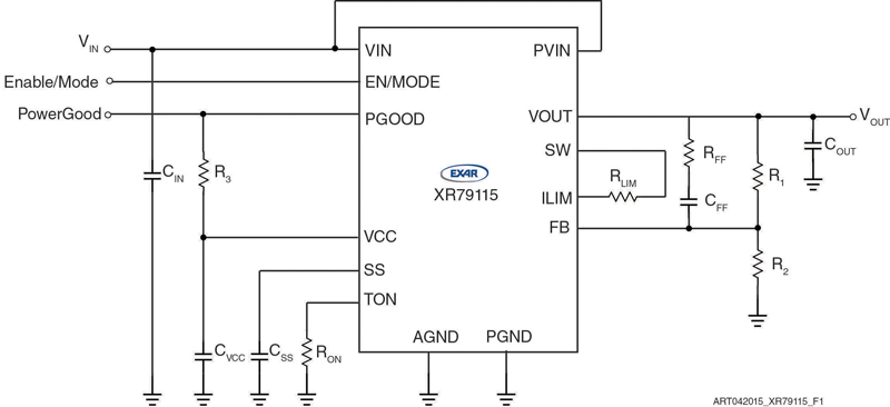
As illustrated, a 15A DC/DC converter can be implemented extremely simply using the XR79115 and can be configured using very few external components. By way of an example, Figure 2 shows how this can be achieved. It shows the soft-start capacitor, CSS, as well as the time constant resistor, RON. The On-Time is inversely proportional to the input voltage, VIN.
Click image to enlarge
Figure 2: The output voltage can be easily set using a simple voltage divider as shown
Each switching cycle begins with the GH signal turning on the high-side (switching) FET for the preprogrammed time, after which the high-side FET is turned off and the low-side (synchronous) FET is turned on a preset minimum time (250ns nominally), termed the minimum Off-Time.
Following the Off-Time, the voltage on the FB (feedback) pin is compared to an internal voltage ramp at the feedback comparator; when the feedback voltage drops below the ramp voltage the cycle repeats. The voltage ramp is, in effect, the proprietary emulated current ramp method which makes it possible to use ceramic capacitors.
With its wide input voltage range of 5V to 22V, the output voltage can be easily set using a simple voltage divider as shown in Figure 2. While overcurrent protection is achieved through the integrated hiccup mode, this mode is entered if the load current exceeds the programmed overcurrent limit for four consecutive switching cycles. Once entered, the MOSFET gates are turned off for 110ms, following which a soft-start is attempted. The device will remain in hiccup mode until the load current falls below the programmed overcurrent protection limit (set using an external resistor, RLIM, in our design example).
Perhaps the most important design step in this example application is the selection of the output capacitors. To achieve this, the maximum load current should be known, as well as the maximum acceptable voltage drop. Commonly, the most important factor in this step is knowing the acceptable voltage drop during the transient response. The capacitor value can now be selected, ensuring that the ripple current rating for the selected ceramic capacitor is greater than the RMS current.
Looking forward
The use of Point-of-Load converters in complex systems is increasing and as a result, a wider variety of solutions is emerging. For example, the XR79115 described here targets systems that exhibit fast transient PoLs, including networking and communications, industrial and medical equipment and embedded high power FPGAs.
As distributed power demands continue to increase, the industry will need more highly integrated and efficient step-down DC/DC converters such as the XR79115, providing a high power solution in a low profile footprint. This device measures just 12mm x 12mm x 4mm. Through greater integration and continued development of advanced switching methodologies, all industries can continue to meet the challenges of power density, efficiency and cost-effectiveness.