Which Airflow Direction for Power Supply Fan Cooling?
The best direction of the airflow could depend upon the application, product type and the manufacturer’s recommendations
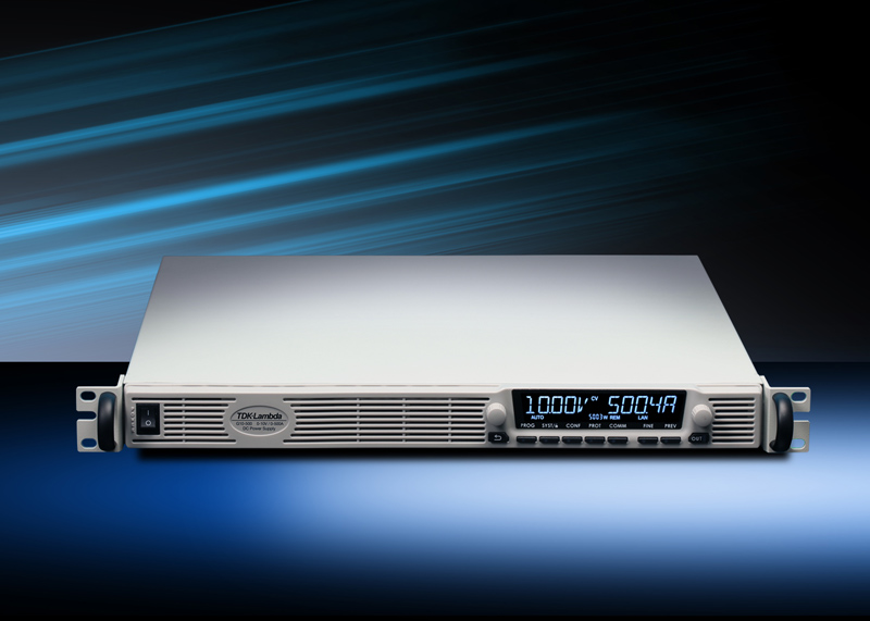
Figure 1: Genesys+ DC programmable power supply
With integral, built-in fans some power supplies have the fan blow cool air into the power supply and others have the fan extract the hot air. The option to have the power supply manufacturer reverse the direction of the fan may be available. This may be of interest to the user when the system and power supply airflow are in different directions. This will minimise back-pressure issues, which can stall the power supply fan and cause overheating.
What determines the direction of a standard product’s airflow will be how the product is to be used, its mechanical construction, operating environment, internal back pressure and reliability.
Fan direction for rack mounted equipment
Rack mounted equipment like the TDK-Lambda Genesys+ series of DC programmable power supplies (Figure 1) have cool air drawn in from the front of the unit and the hotter air exiting out of the rear. Primarily, this to avoid hot air being blown directly at an operator or technician, which can cause discomfort. It is standard with most large racking systems to extract heat out of the system utilising fans mounted on the top or rear of the system cabinet. Ducting may be used to vent the air outside to reduce air conditioning costs.
Cooling of critical components
The physical positioning and direction of the fan inside an enclosed power supply is a decision taken early during a product’s development. Electrolytic capacitors are used for multiple functions inside a power supply and their lifetime is very dependent on their case temperatures. Every 10oC rise in a capacitor’s temperature will halve its operating life, therefore cool air has to be directed accordingly to avoid early field failures.
Capacitors on the input (primary) section are used to store energy to allow the product to continue operating during brief (typically 10 to 20 milli-seconds) losses in the AC power. They are also used in the output filter (secondary) circuitry to reduce high frequency ripple and in the control circuitry. The loss of capacitance due to excessive heat may manifest itself in oscillation on the output voltage, random shutdowns and a failure to restart after a power loss.
Comparing airflow direction on heat sensitive components
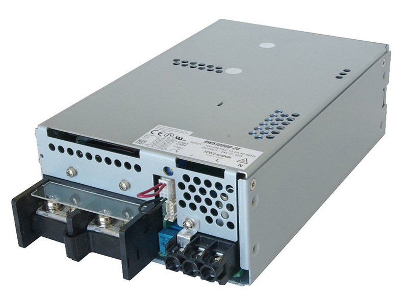
As an example, we are taking the TDK-Lambda 1000W RWS1000B enclosed power supply (Figure 2) which has an internal fan and an option for reverse airflow.
Click image to enlarge
Figure 2: TDK-Lambda’s 1000W RWS-B AC-DC power supply
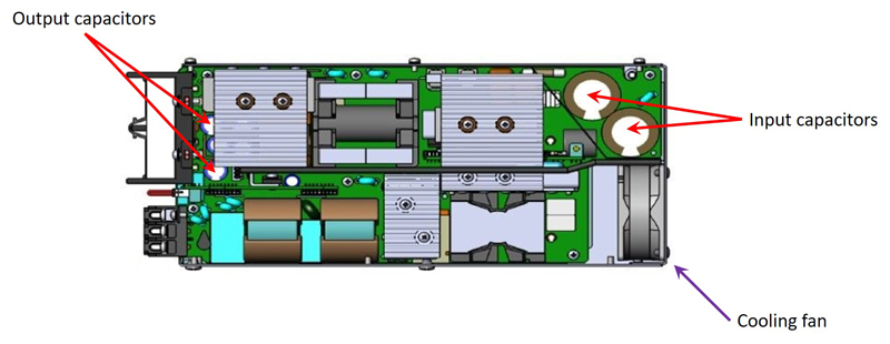
Figure 3 shows the RWS-B’s fan and electrolytic capacitor locations with the cover removed. Using this view we can review the advantages and disadvantages of the fan airflow direction.
Click image to enlarge
Figure 3: Electrolytic capacitors and fan location
The input and output terminals are on the front of the product (left hand side), and the fan is at the rear (right hand side). The red arrows show the location of the heat sensitive input and output capacitors.
Advantages of exhausting the hot air
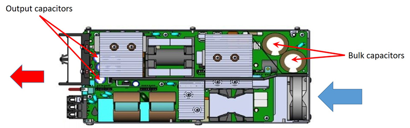
As indicated by the size of the arrows in Figure 4, the speed of the air entering the power supply at the left hand side is lower than the exit speed. This is due to the effective cross sectional area being approximately twice that of the right hand side (the fan). Lower speed air is less likely to draw in outside contaminants (dust and dirt) which could impact product lifetime.

Click image to enlarge
Figure 4 showing the fan blowing air hot air out (exhaust)
Cool air is drawn in from the left of the power supply over the output capacitors, this keeps these components cool and their lifetime is improved.
Disadvantages of exhausting the hot air
The input capacitors will receive warmer air, but the addition of an air-directing baffle and slots or holes positioned in the cover mitigate this. In general, the input capacitors are less sensitive to heat than the output (filtering) capacitors.
The lower speed air cannot easily be directed at hot items like magnetics. Air will always take the path of least resistance
Hot air is drawn across the fan bearings, which could affect fan life. If the fan speed is controlled according to ambient temperature, bearing wear will be reduced. Higher quality or higher temperature fans can also be used.
Advantages of the fan blowing cool air in
As seen from Figure 5, cool air is drawn across the fan bearings, increasing fan life.
Click image to enlarge
Figure 5: Fan exhausts the hot air
The higher speed cool air creates a backpressure and that can be directed at hot areas, like the magnetics, utilising baffles. This may reduce the de-rating of the power supply allowing it to deliver more power at higher ambient temperatures.
Disadvantages of the fan blowing cool air in
The output capacitors may run hotter as the hot air is exiting to the left. Larger and/or higher quality capacitors can be used, which will have less internal heating, run cooler and offset the shortened lifetime.
More contamination may be drawn into the power supply.
Many fan cooled power supplies, like the RWS1000B offer “reverse fan” options on their datasheets. Often, due to reduced or improved thermal performance within the supply and hotter air moving through the fan, the maximum ambient operating temperature may vary.
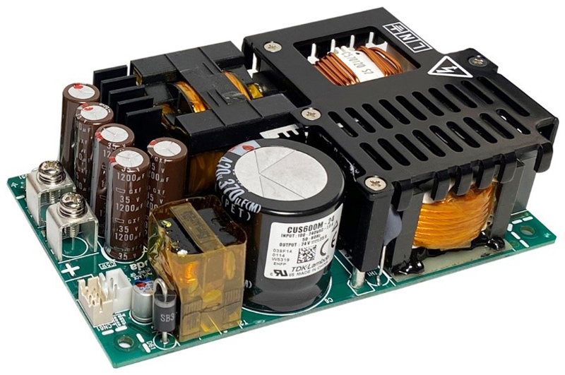
Open frame power supplies relying on system airflow
For this example TDK-Lambda’s CUS600M open frame power supply is being considered (Figure 6). The product is rated for 400W (600W peak) convection or 600W continuous with external airflow.
Click image to enlarge
Figure 6: TDK-Lambda’s CUS600M power supply
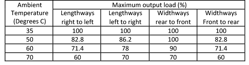
Although there are no concerns regarding an integral fan potentially having back pressure issues, the direction of the system airflow can affect product derating. The CUS600M instruction manual shows that with 2.7m/s airflow the optimum direction is widthways, exiting the side of the large black capacitor. (Table 1). The coolest air is first applied to the main transformer and the power factor correction boost inductor.
Click image to enlarge
Table 1: Percentage derating according to cooling air direction
To provide this data, the manufacturer has taken multiple temperature measurements of the critical components using thermocouples. It is very important to ensure that when making measurements, sufficient time is allowed to enable to temperatures to stabilise.
The CUS600M is also available with a cover and integral fan option. This can simplify system thermal management and avoid the need for making as many temperature measurements.
Use a power supply manufacturer that has local technical support, they will be pleased to advise you on the best choice of product configuration for your system. The manufacturer’s website should have the relevant technical documentation readily available for the user to design the product in and ensure years of reliable, trouble-free operation.


