Why Does Current-Mode Control in Switching Regulators Matter?
Figure 1: The basic working principle of a current-mode regulator
There are thousands of different switching regulators on the market. Selectionis based on specifications such as input voltage range, output voltage capability, maximum output current, and a slew of other parameters. This article explains current mode, a differentiating feature commonly listed in data sheets, and its advantages and disadvantages.
Current-Mode Regulators Explained
Figure 1 shows the basic working principle of a current-mode regulator. Here, the feedback voltage is not only just compared with an internal voltage reference but also with a sawtooth voltage ramp for the generation of the necessary PWM signal for the power switch. The slope of this ramp is fixed in voltage-mode regulators. In current-mode regulators, the slope is dependent on the inductor current and is yielded from the current measurement shown in Figure 1 at the switching node. This is what differentiates current-mode regulators from voltage-mode regulators. Current-mode regulators offer many advantages. One is that the inductor current immediately adapts to changes in the input voltage (VIN in Figure 1). Thus, the input voltage change information is directly fed into the control loop, even before the output voltage (VOUT in Figure 1) tracks this input voltage change.
The advantages of current-mode control are so convincing that most switching regulator ICs on the market work according to this current-mode control principle.
Click image to enlarge
Figure 2: A simplified control loop compensation through current-mode control shown in a Bode plot with just one simple pole in the power stage
Another key advantage is simplified control loop compensation. The Bode plot of a voltage-mode regulator shows a doublepole; a current-mode regulator generates just one simple pole of the power stage at this point. This produces a phase shift of 90°, instead of 180° with a double pole. Thus, a current-mode regulator can be much more easily compensated and thus stabilized. Figure 2 shows the simple transfer function of the power stage of a typical current-mode regulator.
Click image to enlarge
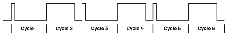
Figure 3: A switch node voltage: a sub-harmonic oscillation with a current-mode regulator
However, a few disadvantages exist alongside the mentioned advantages. Current-mode regulators cannot immediately make the required current measurements after a switching transition because the noise will couple into the measurement strongly at this time. It takes a few nanoseconds for the noise caused by the switching to subside. This is called the blanking time. It normally results in a somewhat longer minimum on-time specification than for voltage-mode regulators. Another disadvantage of current-mode regulators is the possibility, in principle, of a sub-harmonic oscillation. This is shown in Figure 3. If a duty cycle of greater than 50% is required, a current-mode regulator may alternately execute short and long pulses. In many applications, this is considered instability, which should be avoided. To solve this, a certain ramp compensation can be added to the generated current ramp shown in Figure 1. It can shift the critical duty cycle threshold to well above 50% so that even at higher duty cycles, no sub-harmonic oscillations occur.
Even these earlier mentioned restrictions, due to the blanking time and the resultant duty cycle limitations, can be circumvented through the IC design. For example, one remedy is to incorporate low-side current sensing where the inductor current is measured during the off-time rather than the on-time.
Conclusion
All in all, the advantages of current-mode control in switching regulators outweigh the disadvantages for most applications. And through various circuit innovations and modifications, the disadvantages can be bypassed. As a result, most switching regulator ICs today use current-mode control.