With ever-increasing battery energy density, battery management and monitoring is essential to avoid any kind of hazards related to overvoltage or overtemperature
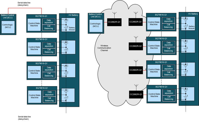
Figure 1: Wired vs Wireless BMS
Batteries in EV/HEV reach nominal voltages of 400 V or 800 V. The batteries are typically organized in modules that are managed by a dedicated battery management integrated circuit (BMIC). Typically, one BMIC can monitor up to 16 cells connected in series.
The main role of the BMIC is to periodically measure the cell voltages and temperatures. These quantities are converted into digital form and conveyed towards a host BMS control microcontroller (MCU). The information from the BMIC is vital for calculating the state of charge and state of health. In the context of BMS, BMICs are also functional safety-relevant.
The requirements for communication in any BMS implementation include:
• Provide the host MCU with a refreshed cell data when requested
• Enable the host by verifying the overall correctness of the data
As illustrated in Figure 1, typical BMICs exchange data with the host MCU over a wired connected in daisy-chain topology.
Since the system cost and battery configuration flexibility are high priorities for car manufacturers, a trend can be seen that the safety-relevant battery data are transferred over a dedicated wireless link within the HEV/EV battery. Using wireless data transfer brings significant savings on cabling, connectors, and isolation components as well as on the assembly time of the complete battery.
A requirement on ASIL D on the system level remains from the wired systems and it translates into an ASIL D-compliant communication error detection in wireless implementations.
The BMICs and the host MCU are basic components of the wired BMS whereas in a wireless BMS, the wired daisy chain is replaced with wireless controllers and appropriate communication protocol.
The wireless controllers from TI are SoCs that integrate an RF physical layer and user-programmable MCU core that may implement communication protocol stacks and application software (SW). These wireless SoCs (WSoCs) are targeted at a wide range of applications, offering various on-chip features while keeping the cost competitive for automotive or consumer products.
The reason for mentioning this is related with a fact that the typical wireless SoCs do not comply with functional safety standards from a random hardware faults diagnostic coverage standpoint.
Communication architectures
Generally, there are two possible architectures for safety-relevant data transmission. They are described in IEC61508-2(2) (a basic functional safety standard available from the IEC Webstore) in section 7.4.11.
• White channel – where complete HW, SW (including transmission protocols) is developed and validated according to functional safety standards.
• Black channel – where end elements including HW, SW (including transmission protocol) comply with functional safety standard and part or parts of the communication channel between compliant end interfaces do not comply with any specific functional safety standard.
Automotive BMICs from TI are functional safety-compliant devices that offer numerous safety mechanisms to help enable system-level capability up to ASIL D according to ISO 26262. A built-in communication protocol enables the host MCU to detect and report the possible communication errors and HW faults.
The wired BMS with a functional safety compliant MCU on one end and functional safety compliant BMIC on the other end are typical examples of a white channel approach. Conversely, the wireless controllers are not functional safety compliant components thus the black channel approach must be used.
Communication errors
One of the most important disciplines in safety-relevant data transmission is the ability of the HW and the SW to detect potential errors. Fortunately, the types of the errors and recommended approaches how to detect them have been standardized.
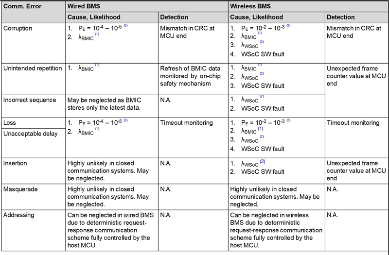
Standards IEC62280 and IEC61784-3 discuss functional safety data transmission implications and requirements which are generally unaffected by the transmission media. These standards give us a summary of types of communication errors and measures that detect them.
Click image to enlarge
Table 1. Wired and Wireless BMS Communication Errors
Evaluation of detection performance
Since the WBMS targets HEV/EV, compliance according to ISO26262 shall be demonstrated on the system level. However, ISO26262 does not provide much guidance on how to address error detection in data communication. The only mention of qualitative requirements are in the following:
• ISO26262 Part 5 – evaluation of data communication diagnostic coverage in Table D.6.
• ISO26262 Part 6 – Exchange of information between software elements in section D.2.4
Diagnostic coverage “high” can be achieved by a combination of three measures:
• Information redundancy
• Frame counter
• Timeout monitoring
Those detection mechanisms must be implemented in WBMS. However; how does one evaluate if they are implemented adequately?
Qualitative – how errors are detected
This section details how the errors are detected:
▪ Information redundancy
• Implemented as CRC16 (end-end)
• Additionally, CRC32 – in WBMS protocol
▪ Frame counter – end-to-end implemented (details are found in the TI WBMS functional safety concept document)
▪ Timeout monitoring – this is straightforward – the host monitors the timeliness of data frames against the fixed and deterministic timing scheme
Quantitative – probability error versus probability of non-detected error
Claiming a high diagnostic coverage according to ISO6262 allows detection of 99% faulty data frames (reference: ISO26262 D.1). It is easy to prove that 99% is not sufficient to achieve ASIL D PMHF for the WBMS communication.
The minimum duration for one frame exchange between host and a single node in TI WBMS equals 2 ms. That gives 1.8 × 10⁶ frames per hour. Worst-case bit error probability as mentioned in Table 1 may achieve values as high as PE = 10–2 (reference: IEC61784-3). This translates to a frame error rate of 1.8 × 10⁶ frames per hour. It is an identical number as the frame rate. Why is this true?
1. PE = 10–2 shows that statistically every hundredth bit is corrupted.
2. Frames are much longer than 100 bits
Therefore, in every frame there is nearly a 100% probability that at least one bit is corrupted.
One might state “When every single frame is corrupted, there is no communication happening at all”. And that is correct. Nevertheless, the system must remain safe by detecting all these errors.
Naturally, this cause of communication errors (electromagnetic interference- EMI) is by far the most probable in the complete communication chain. Therefore, the quantitative error detection performance evaluation focuses solely on EMI-caused errors.
Assuming 1FIT target of residual (undetected) faults (out of total 10FIT for ASIL D) for the communication part of the WBMS, the required diagnostic coverage or better defined as “a probability of non-detection of a communication error” may be back-calculated as:
10–9/1.8 × 106 = 5.55 × 10⁻¹⁵
where:
◦ 10–9 is a failure rate corresponding to 1FIT
◦ 1.8 × 10⁶ is a frame error rate per hour
This value can be achieved by a combination of multiple detection mechanisms.
Implementation of communication protocols
IEC62280 describes a communication error model of the black channel in Annex C. The black channel includes HW, SW, and EMI factor that is responsible for all non-hardware related faults in the communication channel.
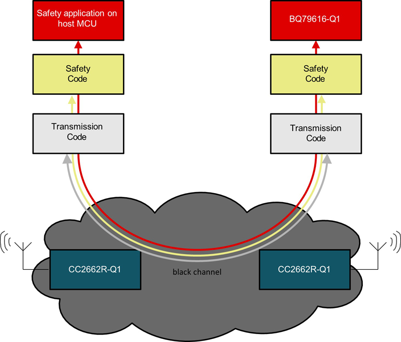
This model is implemented in TI WBMS as two underlying protocols:
1. The first one called “BQ protocol” is an identical end-to-end protocol that BQ79616-Q1 uses for communication over the wired interface. This protocol is implemented in the state machine of the BQ79616- Q1 and a host safety MCU. The BQ protocol runs on both ends on a trusted HW and in IEC62280 nomenclature corresponds with the safety code. On this layer, the following errors are detected:
a. Errors caused by the failure of CC2662R-Q1 at each node (in IEC62280 nomenclature “non-trusted HW”)
b. EMI factor with a detection performance of implemented IBM polynomial CRC-16
2. The overlaying proprietary protocol called “WBMS protocol” runs on CC2662R-Q1 devices. This protocol corresponds to the IEC62280 transmission code. The WBMS protocol serves as a container for BQ protocol frames and features many mechanisms improving security, authenticity, and availability of the communication channel but in scope of functional safety are two mechanisms:
a. CRC-32 detecting EMI-caused data corruptions
b. Four-byte MAC (Message Authentication Code) ensures authenticity and as well integrity of the messages. It adds up to the detection performance of EMI-caused communication errors.
The TI WBMS combines CRC-16, CRC-32, and MIC to detect a sufficient amount of interference-caused communication errors. The calculated probability of error not-detection is: 3.552 × 10⁻¹⁷, or better, depending on the number of wireless nodes and bit error probability of the communication channel.
Click image to enlarge
Figure 2. Structure of Communications Protocols in TI WBMS

Click image to enlarge
Figure 3. Structure of Underlying Data Frames