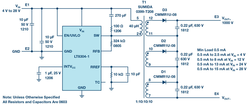
Figure 1. A complete 1000 V/15 mA isolated flyback converter from a 4 V to 28 V input
Isolated flyback converters are used in automotive, industrial, medical, and telecom applications where the power supply must be reliable, easy to use, high voltage, and isolated, and they must provide excellentregulation over load, line, and temperature. LT8304-1 is an isolated, no-opto flyback converter optimized for high output voltage applications that provides outputs up to 1000V.
Traditionally, the regulation feedback loop requires a bulky high voltage divider to directly sense the high output voltage, along with optocouplers to convey feedback information back through the isolation barrier. The bulky resistor solution results because a 1206 resistor can handle 200 V maximum. So to sense 1000 V, at least six 1206 resistors are required, plus a small bottom resistor.
1000 V/15 mA Output, from a 4 V to 28 V Input
An LT8304-1 flyback converter design features a low component count. Figure 1 shows a complete 4 V to 28 V input to 1000 V output solution capable of supporting 15 mA loads. The output current capability increases with input voltage, reaching 13 mA when the input voltage is greater than 24 V. The LT8304-1’s ability to sense the output voltage through the primary side wave form eliminates the need for a bulky high voltage divider, and no optocoupler is required.
The guidelines for calculating voltage and current stress on the components surrounding the LT8304-1 are detailed in the LT8304-1 data sheet. Notably, this 1000 V solution uses a transformer with three split-output windings on the secondary side. The primary side to secondary side turn ratio is 1:10:10:10, instead of a single-secondary winding 1:30 transformer. The 1:10:10:10 transformer enables the output voltage stress to be split among three high voltage output diodes and three high voltage output capacitors. Individual component voltage ratings need only be 1⁄3 of the total voltage, which facilitates more options for output diode and output capacitor selection.
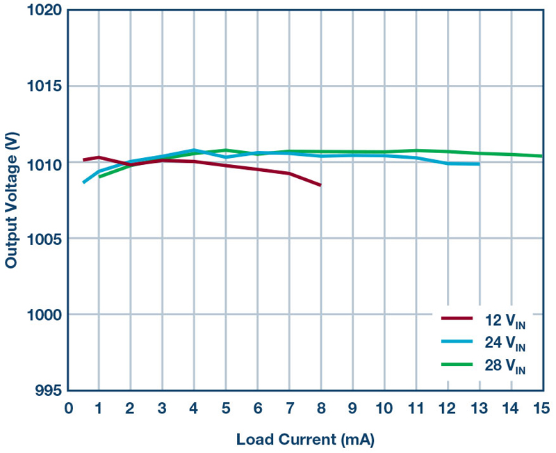
Figure 2 shows this flyback converter reaching 90.5% peak efficiency. Even with no optocoupler, load regulation at various input voltages remains tight, typically 2% to 3%, as shown in Figure 3.

Click image to enlarge
Figure 2. Efficiency of Figure 1 at various input voltages
Click image to enlarge
Figure 3. Load regulation of Figure 1 at various input voltages
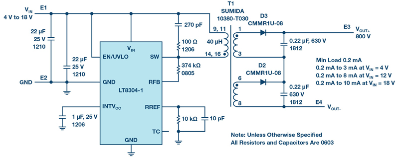
800 V/10 mA Output, from 4 V to 18 V Input
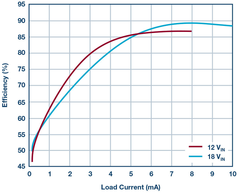
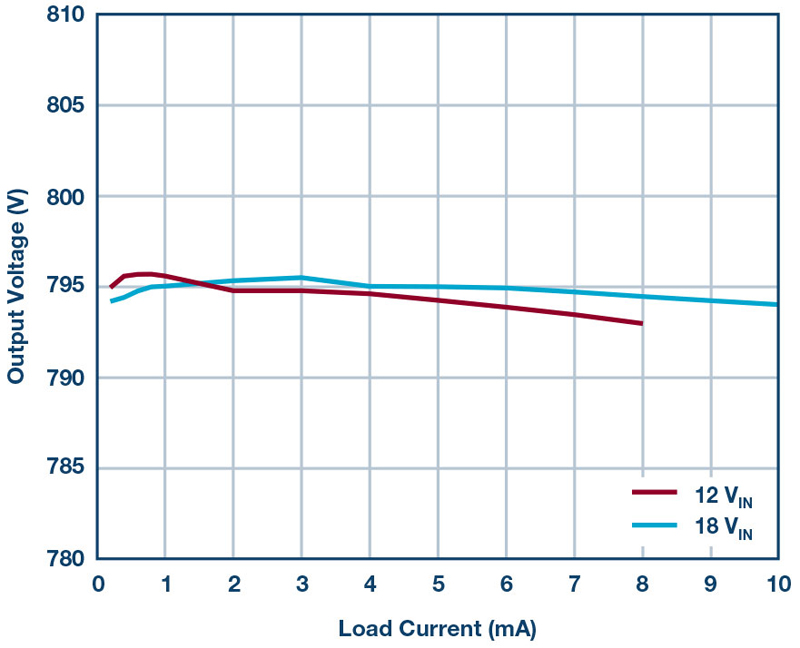
Figure 4 shows a complete 4 V to 18 V input to 800 V output solution capable of providing up to 10 mA output current. This flyback converter achieves 88.2% peak efficiency when the input is 18 V and the load current is 10 mA. Figure 5 shows the efficiency curve at various input voltages; Figure 6 shows the excellent load regulation. This solution also features a low component count.
Click image to enlarge
Figure 4. A complete 800 V/10 mA isolated flyback converter from a 4 V to 18 V input
Click image to enlarge
Figure 5. Efficiency of the solution in Figure 4 at various input voltages
Click image to enlarge
Figure 6. Load regulation of the solution in Figure 4 at various input voltages
Conclusion
The LT8304-1 is an easy to use monolithic micropower isolated flyback converter optimized for high output voltage applications. By sampling the isolated output voltage directly from the primary side flyback waveform, complete solutions maintain tight regulation — requiring neither an output voltage divider nor an opto-isolator.
The output voltage is simply programmed with two external resistors and a third optional temperature compensation resistor. Boundary mode operation enables a small magnetic solution with excellent load regulation. A 2 A, 150 V DMOS power switch is integrated, along with all the high voltage circuitry and control logic, in a thermally enhanced 8-lead SO package. The LT8304-1 operates at an input voltage range of 3 V to 100 V, and delivers up to 24 W of isolated outputpower.