A constant move has been toward nearly exclusive use of stepper motors in most applications
The inexorable drive towards automation and motorized tasks has progressed from the realm of large factories with huge capital investments to the low budget realm of disk drives, robotic toys, scanners and printers in mundane situations. As this drive has occurred, the constant move has been toward nearly exclusive use of stepper motors in most applications. Stepper motor systems and the associated body of motion management technology has developed significantly, and it has served us well. The favor for stepper motors arose from the surge in popularity of digital electronics, and also from the poor performance of analog controllers such as PID controllers applied to DC motors. PID control with DC motors require extensive tuning, and those systems are a consummate compromise between adequate responsiveness and oscillatory behavior. Each system with PID control has to be tuned, and that tuning is usually only valid for a relatively narrow set of conditions.
Even so, systems based on stepper motors are not perfect engineering answers. Stepper motors are more expensive and complicated than comparable DC motors, and that cost disparity increases with motor size. At 1/2 horsepower, a stepper motor costs about 10 times what a dc motor of that size costs, and the requisite control systems are similarly more expensive. Stepper motor systems have the complexities of electronics dedicated to each step forward or backward of the motor, and they require a second computation device and software to drive that electronic controller. As engineering tradition would have it, the software has often been written in arcane languages which challenge all but the most dedicated souls. These factors present an additional challenge in system integration, and drive up the cost of properly engineering them.
Several recent developments now make it reasonable to use alternatives to stepper motor systems. For example, good quality inexpensive DC motors with encoders are now widely available in a wide range of sizes. This factor, coupled with ready availability of inexpensive good quality electronics provides a solid route to the general use of dc motors for speed and position control applications. In addition, there are now DC actuators with position feedback via gear driven potentiometers, These actuators come with a slide system built in, as well as limit switches, so there is a lot less hardware to buy (no stepper controller, slide, limit switches, etc.). This means that the cost of this type of actuation is less than ¼ the price of a comparable stepper motor based system.
There are also system integration factors which make it worth considering the DC motor option. One factor is the electrical noise generated by the stepper system; another is the cost of software engineering for controlling the stepper motor controller. These are not problems with the DC systems with their feedback. The integration of the DC units with feedback into a whole working system is much easier and less expensive in general.
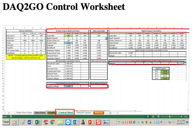
In our laboratories, we have applied a complete system integration tool to many versions of DC motor actuation and motion situations. The system (see DAQ2GO.COM) can take in many different kinds of signals (analog, digital, frequency, etc.), and then output signals (current, etc.) to control items, including the motion and actuation by DC motors. We have used this system integration tool to control the power for motion, heating, cooling, liquid flow, stress rate and other parameters on a plethora of instruments and devices. We can even drive up to about 1/3 horsepower motors directly without a separate motion control unit.
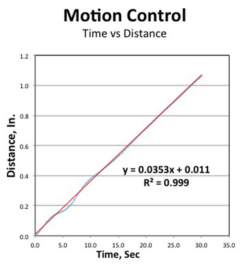
A key and fascinating feature of the system integration tool is that the software portion is based in Excel. We take full advantage of the Excel’s power and flexibility, from its graphics, math and programmability. We have made several targeted, custom applications workbooks from a set of generalized application worksheets and templates associated with all the common system tasks (user interface, real time graphics, communications and i/o control, as well as data post processing. We used this approach to develop a simple, user-friendly worksheet to define and control motion characteristics without resort to another programming language. Other worksheets are dedicated to tasks such as user interface, real time graphics, automated experimentation, and so on. The cells in the worksheets serve as the programming medium. See Figure 1 Motion Control – Time versus Distance
Click image to enlarge
Figure 1: Motion Control – Time versus Distance
Although we have a PID controller algorithm on the control worksheet, we have found that simple but smart control algorithms are much better performing and much more universal. We use smart algorithms now and have replaced the rather obsolete PID type control.
The performance of the DC motor with its continuous range of speeds and power, coupled with the real time current and position control has allowed us to do facile motion control of crosshead speed on a press during which resistance to crosshead motion varied over 100 fold. The correlation coefficient of crosshead position versus distance was > 0.999!
Click image to enlarge
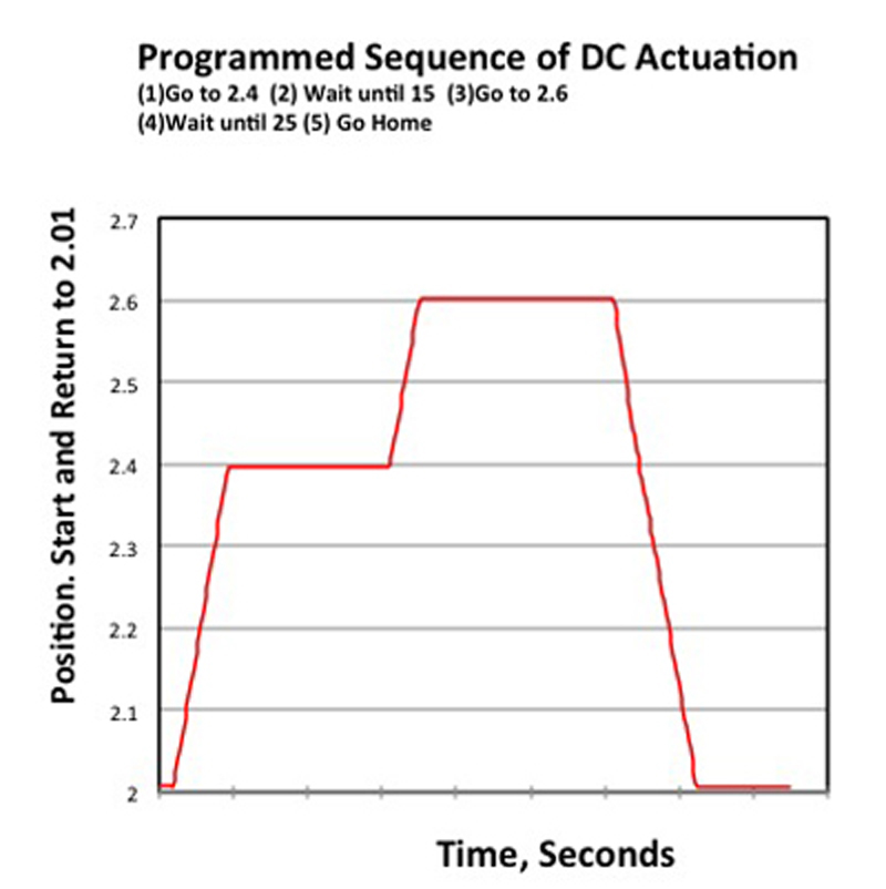
Figure2. Programmed Sequence of DC Actuation
On the same press with the same test material and software, travel rates from .060”/min to 30“/min were similarly controlled, and there was no tuning involved.
We have found that Excel can work very well as the defining medium for motion control. The speed, duration, end location, acceleration and deceleration of a dc actuator can be described explicitly and simply in cells on a worksheet dedicated to control. The plot in Figure 2 shows the time varying location of the tip of a CD actuator. This motion was simple to program on the control worksheet. For the sake of clarity and simplicity, Single cells was used for each of the motion sections. Tutorials and examples can be found on youtube.com videos using “daq2go” as the search term.
Click image to enlarge
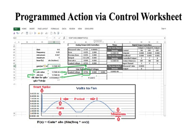
Figure3. Programed Action via Control Worksheet
In a similar vein, the time variation of a DC fan speed, including a ‘kick start’, a minimum speed, and the time-based sinusoidal fan speed variation were simple to accomplish using cells on the spreadsheet. The flow of control goes from the (1) (user defined voltage) to Cell that checks for time, thence to one that checks for minimum output voltage, to a calculation of the desired voltage, and so on. For clarity, each if these program branches (“=if”….) are contained in a separate Excel® cell, although one can have up to 7 program branches in a single Excel cell! The contents of the relevant cells are given in figure 4. (For clarity, ‘K4’ is the elapsed time, in seconds, from start.)
Click image to enlarge
Figure 4. Programming Motion with Control Worksheet Cells
This combination of capabilities –real time data logging, graphics and control is also useful for prototyping systems and procedures. For example, one can disable the control portion of the software, connect joy sticks to the actuators and then log the motion caused by using the joy sticks. This log of time vs position then can serve as the time based motion control reference for the control sheet in subsequent runs. In this way, a simple implementation of ‘learning mode’ is achieved.


