Eco-sustainable projects that get the most out of resources are at the basis of modern energy policies
Agip’s Italian electric energy production uses fuel obtained from the mineral oil extraction process that takes place in the Oil Center of Torrente Tona di Rotello, in the province of Campobasso. The electric energy produced here is used to advantage in the national electricity distribution main controlled by ENEL (the Italian Electricity Board).
The Agip plant has been extracting mineral oil for several years. This oil is subsequently used in refining processes. Extraction leads to the presence of well gas, which is usually unsuitable for use as it is unless specially designed machines are employed to enable combustion. The gases at the well outlet are a mixture of natural gas, other fuel gases, water vapor and so forth. Until only a short while ago, these gases were burnt in torches. They were dispersed and wasted in those flames that we often see burning at the top of gigantic pylons near extraction plants.
It was evident that sooner or later the Agip managers would have wanted to find out how this potential could be utilized particularly in times like these, when energy is precious and its recovery goes hand in glove with those environmental policies about which public and private sectors are finally becoming aware. In cases like these, the experience and skill of partners when research is carried out to identify the best solution is of fundamental importance. This is why Cefla Scrl was contacted as this group works in various industrial fields, amongst which the energy and co-generation sectors.
For the technicians in Cefla’s Plant Division, the target was to use the extracted fuel gases, filter them and make them fit to fuel the largest possible number of generators and create a profitable power station. Cefla proved that it was able to provide Agip with the “turnkey” project, covering the building works to the generators, the automation and monitoring software to plant management and the actual staff members.
The fully successful results obtained now allow Agip to use a 20,000 kW power station where electricity is produced by a system formed by 8 generators driven by engines powered by the very same gas that was previously “burnt” in the atmosphere. The power station is run by an avant-garde automation system based on a PLC network in Profibus FMS and two PC stations based on the Scada Movicon system for supervision and monitoring purposes.
Structure of the power station
The power station designed, built and run by Cefla includes a network of eight 16-cylinder engines manufactured by the Norwegian company Bergen. Each one is connected to a generator, which produces around 2,600 kW. The engines are the internal combustion Otto type and are fuelled with the well gas extracted at the same time as the oil, plus the process gas, i.e. the gas from the three-phase separators in the Agip plant.
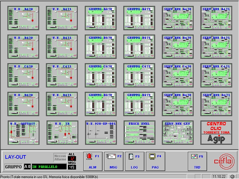
The utilities correlated to each electricity production unit need to be monitored. These utilities include the engine oil feeding circuit, the cooling circuit using water with glycol additive, the air compressors, the filtering system, the ventilation circuit of the engine room, the gas and gas vent on-off valves, the safety devices, the automatic engine stopping and starting mechanisms (see Figure 1).
Click image to enlarge
Figure 1: Main page of AGIP’s mineral oil extraction plant in Torrente Tona. Special objects called “Embedded synoptics” are used to represent the real status of the project.
Besides monitoring the generating plants as they operate, the system also automatically controls the electric energy produced and conveyed to the ENEL network, operating the IG circuit-breakers on each generator and the IR mains circuit breaker on the backbone line that links to ENEL’s national distribution network. Besides being conveyed to this latter, the energy is also used in the power station itself where it powers the electrical users of the plant auxiliaries.
Automation architecture
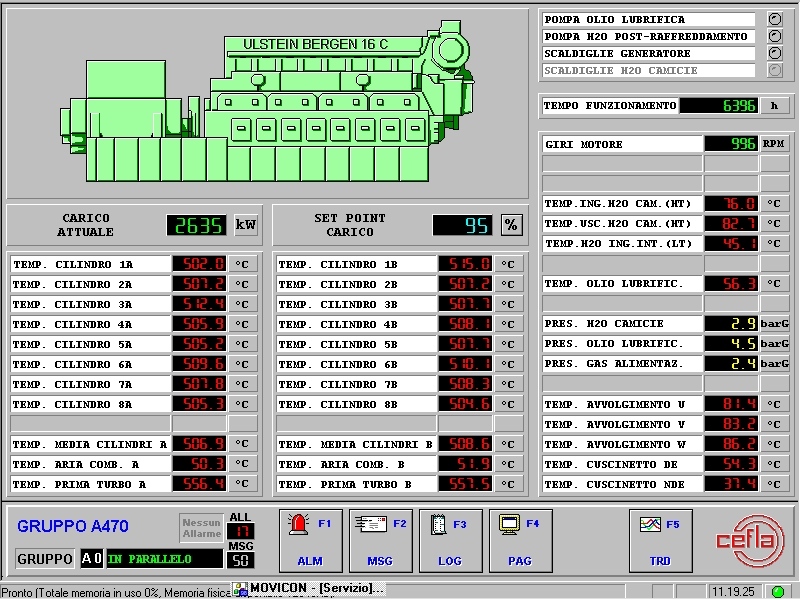
Each of the eight generating plants is monitored by an equal number of graphic synoptics like the one shown in Figure 2. The architecture of the automatic system that controls the entire production plant has been designed to ensure reliable operation and to integrate the components.
Click image to enlarge
Figure 2: Each of the eight generating plants is monitored by an equal number of graphic synoptics
Cefla Impianti chose two partners for these automation techniques: Progea with the Movicon software system for the Scada platform and Siemens for the programmable logic systems.
The following factors were considered as fundamental when the system was planned:
• easy maneuvering for the controls and adjustments;
• easily identified alarms;
• separated circuit equipment or various systems to prevent maneuvering and/or interpreting errors;
• correct and immediate identification of the emergency equipment plus their protection to avoid maneuvering errors;
• easy operation when it comes to servicing and replacing components.
The monitoring system of the electricity main provides the following functions:
• Acquisition and control of the signals to and from the field;
• Display and historic cataloguing of the alarms;
• Management of local and remote controls;
• Communication with external units;
• Functional calculations (compensated measurements, etc.);
• Adjustment;
• Monitoring and management of the electricity main;
• Autodiagnosis.
The PLC-based monitoring systems
Cefla Impianti uses a network of Siemens PLCs in a mixed configuration, featuring a main network based on the PROFIBUS-FMS standard with redundant loop cable in optic fiber and a secondary network of the Siemens MPI type to connect the self-standing monitoring devices of the generating units.
An S5-155H PLC with redundant configuration installed in the main control room handles the common functions of the entire power station plus the functions that interface with ENEL’s network. An S7-400 PLC handles the operation of the auxiliary users and monitors the electricity production part for each generator. Moreover, each engine has its own S7-315 monitoring unit.
The main monitoring PLC consists of 5 racks, 2 main ones and 3 extensions. Two CPUs, one for each main rack, guarantee operating redundancy. Both CPUs control the process together while the user program, the data blocks and the contents of the process images are kept up to date by the coupling lines. The system conducts the self-test functions every 5 ms. If one of the CPUs breaks down, the system continues to operate correctly with the other processor.
The redundancy concept also applies to all the critical I/O of the system, where two outputs (one for each partial central device) or three inputs (one for each partial central device and one for the extension device) are used for each signal. If faults occur in one of the redundant boards, they are localized and passivated until successive replacement, thus guaranteeing continuous service. The less critical I/O signals are handled in the shared mode by means of the boards installed in the extension device.
Main PROFIBUS-FMS network
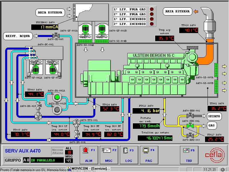
Each generating plant is provided with a series of users, each of which is centralized and common to all plants (see Figure 3). As hardware backup, optic fiber cable is used (62.5-125) in the redundant loop configuration with PROFIBUS FMS protocol at a speed of 1.5 Mbaud.
Click image to enlarge
Figure 3: Each generating plant is flanked by its auxiliary users, and all the functional parameters are represented by animated objects
The communication processors in the PLCs, the communication boards in the PCs and the optic connection module are an integral part of the communication network.
The communication system provides monitoring procedures for the information in the network in order to prevent this from being subjected to alterations as it transits. The network architecture is the Master/Master type and the network traffic is handled by a “token” that passes from one participant to the other in cycles. The participant that possesses the “token” is enabled to transmit information to the others.
A network of electric parameter indicators connects the modules that acquire the electrical parameters located in the various monitoring panels and the main monitoring PLC that acts as a Master. RS 485 communication with MODBUS-RTU protocol at a speed of 9.6 kbaud is used as hardware backup. The information obtained from the individual modules is send to the respective engine monitoring PLCs.
Supervision
Plant supervision is based on a Scada Movicon software platform. Cefla has been using Movicon as software platform for its automation applications for quite a long time, both in the Plant Division and in other operating sectors of the group. The decision to do this was based on Windows NT being used as standard for the automation systems and this led to selection of a SCADA platform able to provide potential, flexibility and compliance with the Microsoft standards (thus assuring reliability and easy use).
Flexibility and the ability to inter-operate with the Microsoft Office line of products was particularly appreciated. When it comes to the methods applied in Cefla’s software planning departments, all this considerably speeds up the time it takes to develop new applications. Movicon also proved to be fully satisfactory in a critical configuration like the Agip plant in the Torre Tona Oil Center, a configuration with around 20,000 Tags to supervise.
Plant supervision thus includes two redundant PC stations, each of which is connected to the plant by the Profibus FMS optic fiber network able to display the process parameters and allow the operator to control the system. One station is installed in the control room of the electric energy generating building while the other is in the control room of Agip’s Oil Center.
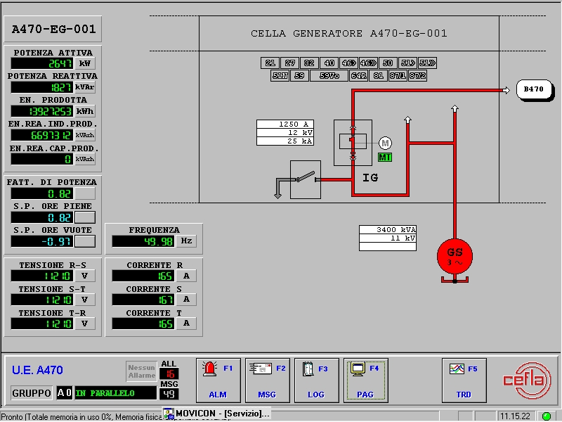
All the parameters and electricity values produced by the plant are monitored and historically catalogued (see Figure 4).
Click image to enlarge
Figure 4: The synoptic that represents the electricity network of each individual generating plant
In addition to the two supervision stations, each monitoring board has an Operator Panel for local display of the alarms and analogue values in the PLCs.
The supervising system provides the following functions:
• It displays the operating statuses of the plant;
• It acquires the commands given by the operator;
• It displays alarms;
• It displays trends;
• It manages historic archives.
The system software carries out all the monitoring, diagnostic and control functions, thus providing the operator with everything he needs to operate the plant on a continuous yet simple basis.
Connections to the supervising system can also be made from remote stations since the operator station, which is located in the control room of the electricity generating building, is linked via modem to the telephone line.
Graphic Synoptics
Particular care was taken when the synoptic masks were created as the operators to run the plant use them. Here, the strategy was based on simple use for the operators while speeding up the development phase. The planning engineers in Cefla’s Plant Division decided to use the standard tool bar for surfing through the synoptics of the supervisor. Each page consists of two synoptic windows, one with graphic representation of the area in question and the other with the tool bar for surfing the system which self-configures to suit the synoptic selected.
There is a page with the general layout of the plant in simplified form. This has been divided into zones characterized by the main components of each and linked together by the main connection lines (electric cables, ducts and pipes). This mask allows the operator to switch to the next synoptic masks by simply selecting the corresponding zone with the mouse.
A large number of synoptics allow the plant values to be analyzed. The Historic Trends enable an accurate analysis to be made of all the basic parameters of both the utilities and electricity users.
The other graphic masks represent the synoptics animated with the process lines and equipment, plus the relative instruments. Each of these has been set up so that it displays the values of the measurements of each individual analogue variable, the status of the equipment (pumps, valves, electric lines, etc.) and the alarms concerning analogue or digital variables.
Alarms
Alarms are displayed in chronological order. The operator has a command so he can recall already identified alarms that are still activated (from the less recent to the most recent). All the events are recorded and stored in Historic Log files that the operator and service engineer can analyze with the selection criteria desired (by date, by priority, by event, etc.).
A synoptic with Operating Messages shows the status of the most important signals in the plant by displaying their corresponding messages in text format. Along with an indication as to the date and time, these operating messages are memorized in the Historic Log files whenever the status changes.
Plant Time synchronizing
The Movicon supervising system handles and synchronizes the time settings of the system for all network participants. In particular, one of the two Scada stations acts as master and, thanks to the integrated functions, sets the time and date of the operating system of the second station and of all the PLCs and Operator Panels.
Thanks to Roberto Sentimenti (Cefla) and to Dr. Bortolato (Agip Petrols)


