Challenges and solutions for driving and diagnosing LEDs
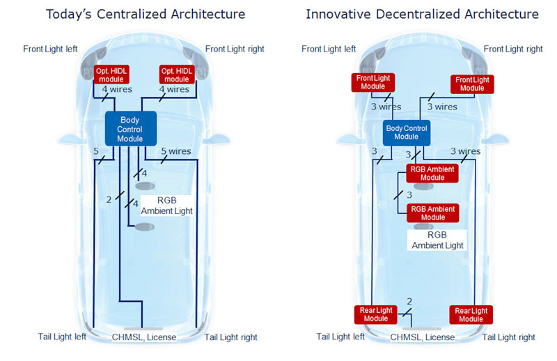
Figure 1: The new innovative body architecture allows a significant wire harness reduction in comparison to today's architecture
One of the latest automotive design trends is LED lighting. LEDs (Light Emitting Diodes) are used for tail lights, interior lights such as ambient lighting, and LED front lights. Front light LEDs enable brand recognition beyond the typical car attributes. In addition to the new design possibilities, reliability and reduction of fuel consumption are key arguments for LED instead of bulbs. However, this new light source challenges the car electronics architecture as well as the fault diagnostics, which is required for maintenance, security and legal perspectives. Those challenges and solutions are explained in this article. The typical body electronics architecture for exterior and interior lighting consists of a body control module (BCM), wires and the light sources as shown in figure 1. The BCM includes communication interfaces (i.e. CAN, LIN), micro controllers, intelligent semiconductor switches, and driver ICs. Control and diagnosis of the loads is realized by integrated semiconductor switches such as Infineon's latest PROFET+ family within the BCM. Usually, the BCM is mounted in the passenger or engine compartment in plastic or partial aluminum housings. Body electronic architectures supporting LED lamps are very similar, but there is more intelligence required directly at the light source, i.e. the LED. LEDs need to be driven with a constant current. Infineon offers for each application a suitable LED driver: - Basic LED Driver: Linear current sources for low to medium brightness LEDs - Power LED Driver: DC/DC converters and controllers for high brightness LEDs - LIN LED Driver: LIN controlled LED driver for RGB or multicolor ambient lighting (under development) Today the BCM's tasks are becoming greater, because more electrical functions are established (e.g. ambient lighting) and included within it. Consequently, the physical dimensions of the BCM should not be increased. This conflicts with the required space for additional semiconductor devices but also with the maximum power dissipation. Today there are many car platforms where LEDs are not used for all car variants. Therefore, the BCM should support driving bulbs as well as LEDs, so that only the light source is differing. This requires smart concepts for the diagnostic, which is discussed later in this article.
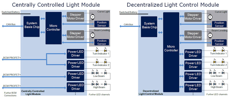
New light features like AFS (Adaptive Frontlighting Systems) require extensive functionalities and intelligence. They are usually implemented directly in the LED lamp, which is shown in figure 2. Therefore, in either case, the required PCB (Printed Circuit Board) contains a micro controller and a system basis chip. Thus, the step to an innovative body electronic architecture is not so significant. In other words: All functions like dimming, diagnostics or fail safe actions could be done directly inside the smart decentral lamp module. The intelligence and power of the LED module are increased on one hand, on the other hand the above mentioned BCM limitations are relaxed. E.g. A failing LED would be reported via a bus interface like CAN or LIN to the BCM. Furthermore, another LED could be activated in dimmed mode to replace the failing LED function. Figure 1 compares today's body architectures to potential innovative decentral architectures mainly supported by LED lamps, because some of the required hardware such as PCB is already present. Smart decentral light modules inside the LED lamp require only a protected supply line and the bus lines as a connection to the BCM. This reduces the cars wire harness. For example: for the left tail light with five light functions, five power wires would be replaced by only one power wire and one or two bus wires (ground connection locally). The new concept reduces wire harness cost but also car weight. Another benefit is that additional diagnostic features can be realized easier, e.g. diagnostics for each LED or LED-chain.
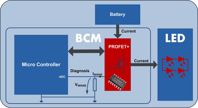
What are the Challenges for the Diagnosis? Especially in the automotive area it is often required to know the exact load status. This is guaranteed by a quick diagnosis in case of a malfunction and serves the user's convenience and protection. In the following the diagnosis of a LED light-module is described in detail on a decentralized architecture. Figure 3 shows a possible simplified BCM in connection to a LED module. The protection and diagnosis for the load's status is realized with a micro controller that interprets the sense signal of a PROFET+. The BCM is usually designed to drive different types of loads with varying current profiles and therefore has to offer flexibility to make the connected load interchangeable. There are several critical cases, which endanger the electronic components or the user's safety. These are the most common failures of the load-side: - Short Circuit: Connection to battery or to ground - Open Load: Failure of the whole LED-module / partial module fail A short circuit to battery or ground is a well known issue that is highly safety relevant, if no protection is available. We will not go into more detail for this case as the high short circuit robustness of the latest generation of high-side switch offers good protection, and the diagnosis is now a standard procedure. The open load scenarios are more challenging for the diagnosis circuits and the micro controllers' interpretation of the signal. Especially if a pure bulb solution is replaced by a LED module after some car facelift or upgrade, the current range changes significantly. While a front light architecture with bulbs uses typically an H1 55W bulb for the low beam (LB) and an indicator (IND) with a P21/27W bulb. Equivalent LED solutions offer a comparable brightness with only 30W or 4W respectively. Solution Watts DC Current Bulb LB 55W 5A LED LB 30W 1A Bulb IND 21W 2.7A LED IND 4W 0.2A While the bulb failure causes a difference of several amps and is easy to detect, the LEDs require more accurate diagnosis circuits. How can we realize the diagnosis for LEDs? As mentioned before, the diagnosis is performed by the micro controller, which receives an analog sense signal (VSENSE) from the PROFET+ and converts it to a digital value for the interpretation through the software. The ISENSE current is proportional to the load current, which is converted to a voltage VSENSE via a sense resistor. Therefore one of the main drivers for the secure load state detection is the accuracy of the sense current from the high-side switch. Infineon's new PROFET+ switches can reach a sense accuracy of up to +/- 5.5% in higher current ranges, which makes them the most accurate devices on the market. Assuming the complete loss of a LED light function such as the low beam would require a high-side switch sense accuracy of approximately +/- 30%, depending on the sense resistor and ADC accuracy. However, some light functions are built up of several LED chains (see figure 2, turn indicator), which means a fail of one LED leads to a loss of one chain, while the other chain is still working. This is not detectable by the BCM, because the physical limit of the system accuracy is surpassed. It requires a complete deactivation of the entire light function at the centrally controlled light module or a diagnosis at the decentralized light control module as shown in Figure 2 to make it detectable. For more information on Infineon Automotive Lighting Products please visit: www.infineon.com/lighting www.infineon.com


