Battery Stack Monitor Maximizes Batteries in Hybrid and EVs
Lithium-ion (Li-Ion) batteries are a popular way to store energy in electric and hybrid vehicles as they offer the highest energy density
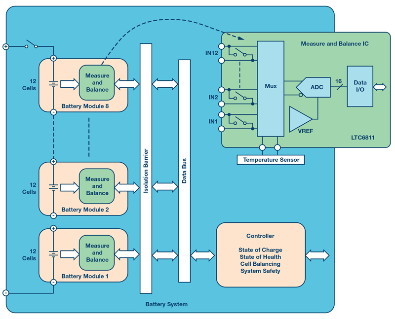
Figure 1. A 96 cell battery pack architecture with the 12-channel LTC6811 measurement IC.
To maximize performance with li-ion batteries, a battery monitoring system (BMS) is mandatory. BMS not only allows you to extract the highest quantity of charge from your battery pack, but also lets you manage the charge and discharge cycles in a safer way, which results in an extended life.
Accurately measuring a battery’s state of charge (SOC) increases battery run time or decreases weight. A precise and stable device does not require factory calibration after PCB assembly. Stability over time improves safety and avoids warranty problems. A self-diagnostics feature helps reach the right automotive safety integrity level (ASIL). A battery pack is a challenging environment for electromagnetic interferences (EMI), so special care has been put into designing the data communication link to ensure robust and reliable communication between the measurement chips and the system controller. Cables and connectors are among the main causes of failures in battery systems, so wireless solutions should be considered.
Introduction
An energy storage unit has to provide high capacity and the ability to release energy in a controlled manner. Storage and release of energy, if not properly controlled, can result in a failure of the battery and ultimately fire. Battery failure can come from mechanical stress or damage, electrical overstress in the forms of deep discharge, overcharging, overcurrent, and thermal overstress. To reach the highest levels of efficiency and safety, a battery monitoring system is required.
The main function of the BMS is to keep any single cell of the battery pack inside its safe operating area (SOA) by monitoring the following physical quantities: stack charge and discharge current, single cell voltage, and battery pack temperature. Based on these quantities, not only can the battery be operated safely, but also SOC and state of health (SOH) can be computed.
Another important feature provided by the BMS is cell balancing. In a battery stack, single cells can be arranged in parallel and in series to achieve the required capacity and operating voltage (up to 1 kV or higher). Accurate cell balancing is a significant feature in a BMS, enabling safe operation of a battery system at its highest capacity.
BMS Architectures
An electric vehicle battery consists of several cells stacked in series. A typical stack—with 96 cells in series—when charged at 4.2 V can develop a total voltage in excess of 400 V. Higher voltages can be reached by stacking more cells. Charge and discharge current are the same for all the cells, but voltages have to be monitored on every single cell. To accommodate the cells required for high powered automotive systems, batteries are often divided into modules, and distributed throughout available spaces in the vehicle. A modular design can be used as the basis for very large battery stacks. It allows battery packs to be distributed over larger areas for more effective use of space.
Analog Devices has developed a family of battery monitors capable of measuring up to 18 series connected cells. The AD7284 can measure 8 cells, the LTC6811 can measure 12 cells, and the LTC6813 can measure 18 cells.
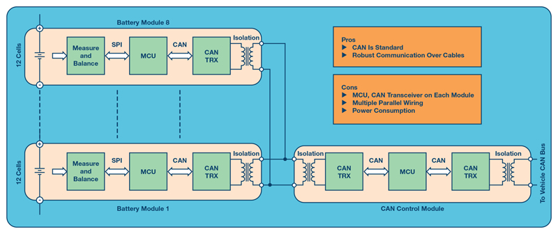
To support a distributed, modular topology within the high EMI environment of an EV/HEV, a robust communication system is required. Both isolated CAN bus and ADI’s isoSPI™ offer road-proven solutions for interconnecting modules in this environment.1 While the CAN bus provides a well-established network for interconnecting battery modules in automotive applications, it requires a number of additional components. The primary downside of a CAN bus is the added cost and board space required for these additional elements. Figure 2 shows a possible architecture based on CAN. In this case, all modules are parallel connected.
An alternative to a CAN bus interface is ADI’s innovative 2-wire isoSPI interface.1 Integrated into every LTC6811, the isoSPI interface uses a simple transformer and a single twisted pair, as opposed to the four wires required by the CAN bus. Figure 3 shows the architecture based on isoSPI and using a CAN module as a gateway.
There are pros and cons to the two architectures presented. CAN modules are standard and can be operated with other CAN subsystems sharing the same bus; the isoSPI interface is proprietary and communication can happen only with devices of the same type. On the other hand, the isoSPI modules do not require an additional transceiver and the MCU to handle the software stack, resulting in a more compact and easy-to-use solution. Both architectures require a wired connection, which has disadvantages in a modern BMS, where routing wires to disparate modules can be an intractable problem, while adding significant weight and complexity. Wires are also prone to pick up noise, leading to the requirement for additional filtering.
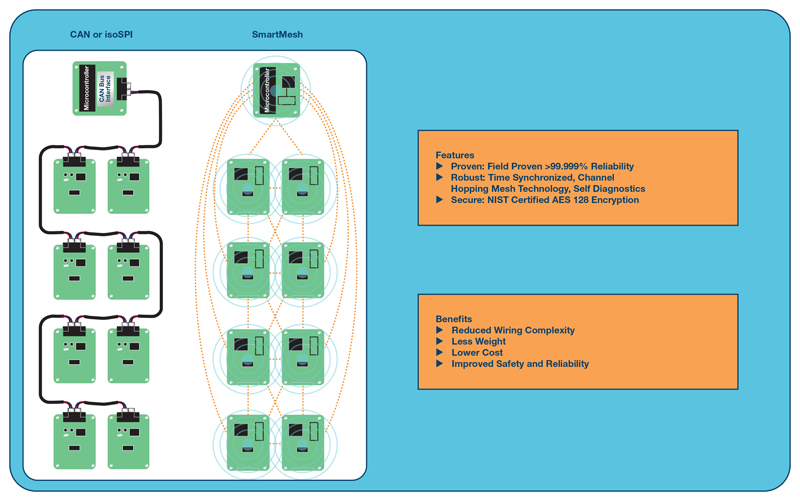
Wireless BMS
Wireless BMS removes the communication wiring.1 In a wireless BMS, each module is interconnected via a wireless connection. The biggest advantages of a wireless connection for large multicell battery stacks are:
u Reduced wiring complexity
u Less weight
u Lower cost
u Improved safety and reliability
Wireless communication is a challenge due to the harsh EMI environment, and the RF shielding metal posing as obstacles to signal propagation.
ADI’s SmartMesh® embedded wireless network, field-proven in industrial Internet of Things (IoT) applications, delivers >99.999% reliable connectivity in industrial, automotive, and other harsh environments by employing redundancy through path and frequency diversity.
Click image to enlarge
Figure 2. Parallel independent CAN modules.

Click image to enlarge
Figure 3. Series modules with CAN gateway.
The Importance of an Accurate Measurement
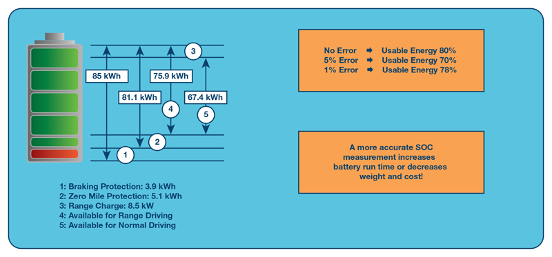
Accuracy is an important feature for a BMS and is critical for LiFePO4 batteries.3,4 Let’s consider the example in Figure 5. To prevent overcharge and discharge, the cells of the battery are kept between 10% and 90% of full capacity. In a 85 kWh battery, only 67.4 kWh are available for normal driving. If there is a measurement error of 5%, to continue to operate the battery safely, the cells must be kept between 15% and 85% of their capacity. The total available capacity has been reduced from 80% to 70%. If accuracy is improved to 1%, the battery can be operated now between 11% and 89% of full capacity, with a gain of 8%. With the same battery and a more accurate BMS, automobile mileage per charge is increased.
Circuit designers rely on data sheet specifications to estimate the accuracy of a cell measurement circuit. Other real-world effects often dominate the measurement error. Factors affecting the measurement accuracy include:
u Initial tolerance
u Temperature drift
u Long-term drift
u Humidity
u PCB assembly stress
u Noise rejection
Click image to enlarge
Figure 4. Battery monitoring interconnections comparison.
Click image to enlarge
Figure 5. Battery charge limits.
A good technology must consider these factors to deliver very high performance. Measurement accuracy of the IC is primarily limited by the voltage reference, which is sensitive to the mechanical stress. Thermal cycling during PCB soldering stresses silicon. Humidity is another cause of silicon stress as water is absorbed in the package. Silicon stress relaxes over time, leading to long term drift of the voltage reference.
Battery measurement ICs use either a band gap voltage reference or a Zener voltage reference. IC designers use an NPN emitter-base junction operating in reverse breakdown as a Zener reference. Breakdown occurs at the surface of the die. These junctions are noisy and suffer from unpredictable short- and long-term drift. The buried Zener places the junction below the surface of the silicon, well away from contamination and oxide effects. The result is a Zener with excellent long-term stability, low noise, and relatively accurate initial tolerance.
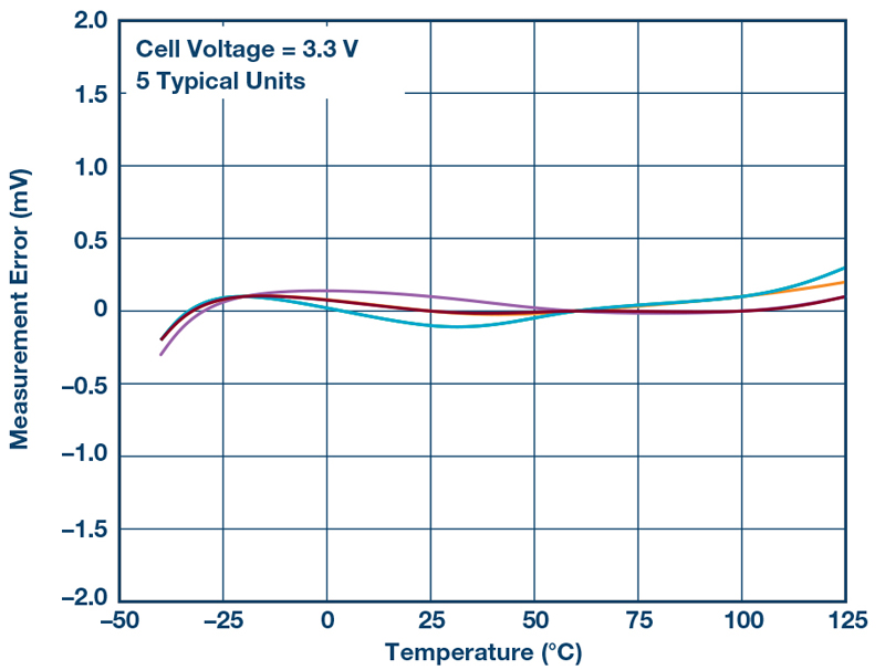
The LTC68xx family uses a laboratory grade Zener reference. Figure 6 shows the drift over temperature of the battery measurement IC error for five typical units.
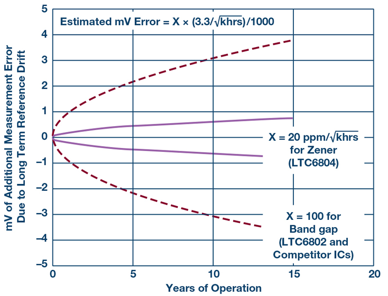
Figure 7 shows a comparison of the long-term drift for a bandgap voltage reference IC and a buried Zener voltage reference IC. The picture clearly shows a much better stability of the Zener reference over time, at least 5× better than bandgap reference. Similar tests for humidity and PCB assembly stress show the superior performance of the buried Zener over the band gap voltage reference.
Click image to enlarge
Figure 6. LTC6811 measurement error vs. temperature.
Click image to enlarge
Figure 7. Long-term drift comparison between buried Zener diode and bandgap voltage references.
Another limiting factor for accuracy is noise. A car battery is a very harsh environment for electronics due to the electromagnetic interference generated by the electric motor, the power inverter, the dc-to-dc converters, and other high current switching systems in an EV/HEV. The BMS should provide a high level of noise rejection in order to maintain accuracy. Due to the high number of cell voltages to be converted and transmitted, the conversion time can’t be too slow. SAR converters might be the preferred choice, but in a multiplexed system, speed is limited by the settling time of the multiplexed signal. In this case, sigma-delta (Σ-Δ) converters can be a valid alternative.
Click image to enlarge
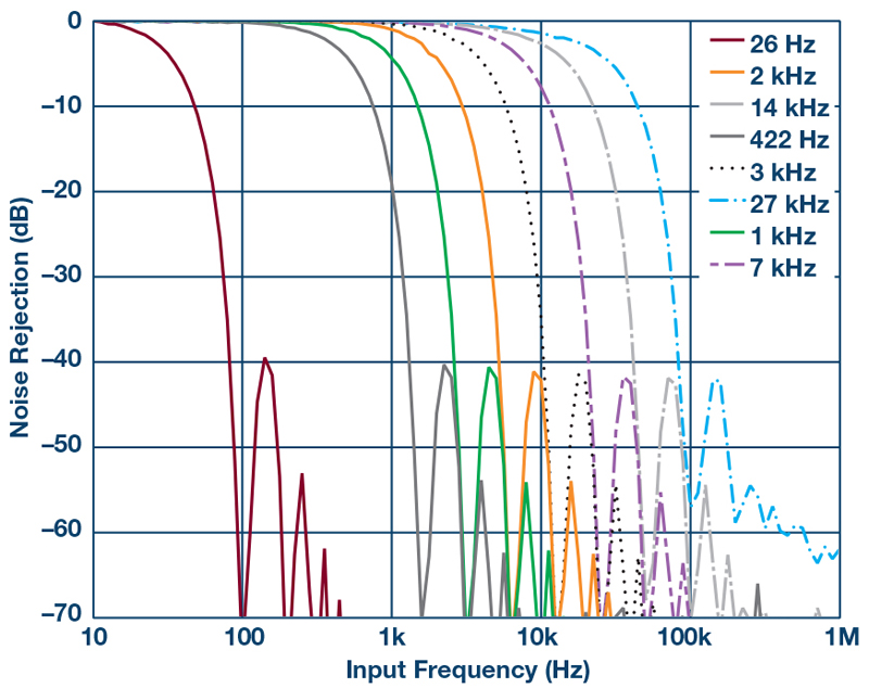
Figure 8. ADC filter programmable ranges and frequency response.
ADI measurement ICs use sigma-delta analog-to-digital converters (ADCs). With a sigma-delta converter, the input is sampled many times during a conversion, and then averaged. The LTC6811 uses a third-order sigma-delta ADC with programmable sample rates and eight selectable cutoff frequencies. Figure 8 shows the filter response for the eight programmable cutoff frequencies..
Cell Balancing for Optimized Battery Capacity
Battery cells, even if accurately manufactured and selected, show slight differences from each other. Any mismatch in capacity between the cells results in a reduction of the overall pack capacity.
Let’s consider our example where the cells were kept between 10% and 90% of the full capacity. The effective lifetime of a battery can be significantly shortened by deep discharge or overcharging. Therefore, the BMS provides undervoltage protection (UVP) and overvoltage protection (OVP) circuitry to help prevent these conditions. The charging process is stopped when the lowest capacity cell reaches the OVP threshold. In this case, the other cells are not fully charged and the battery is not storing the maximum allowed energy. Similarly, the system is stopped when the lowest charged cell hits the UVP limit. Also, there is still energy in the battery to power the system, but, for safety reasons, it can’t be used.
It is clear that the weakest cell in the stack dominates the performances of the full battery. Cell balancing is a technique that helps overcome this issue by equalizing the voltage and SOC among the cells when they are at full charge.5 There are two techniques for cell balancing—passive and active.
With passive balancing, if one cell becomes overcharged, the excess charge is dissipated into a resistor. Typically, there is a shunt circuit which consists of a resistor and a power MOSFET used as a switch. When the cell is overcharged the MOSFET is closed and the excess energy is dissipated into the resistor. Active balancing, on the other hand, redistributes the excess energy between the other cells of the module. This way the energy is recovered and less heat is generated.
Click image to enlarge
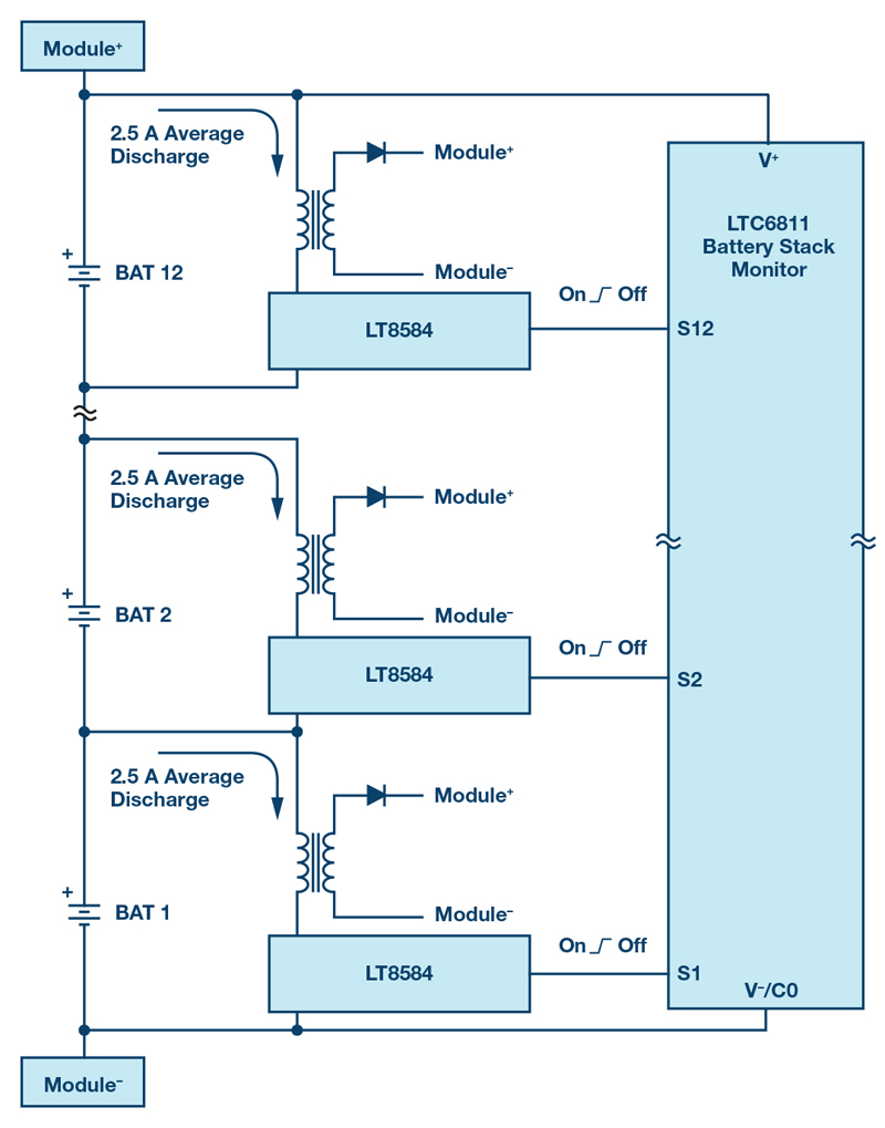
Figure 9. A 12-cell battery stack module with active balancing.
Conclusion
Electrification is key for lower emission vehicles, yet requires a smart management of the energy source—the Li-Ion battery. If not managed properly, a battery pack can become unreliable, and drastically reduce the safety of the automobile. High accuracy helps maximize the performance and the life of the battery. Active and passive cell balancing allow a safe and efficient battery management. Distributed battery modules are easily supported, and a robust communication of the data to the BMS controller, both wired and wireless, allows reliable SOC and SOH calculations.
Analog Devices


