Benefits of Digital-Controlled Programmable AC Power Sources

Programmable AC and DC power sources have been widely used to implement and support a wide range of development and test applications where an engineer needs the ability to fully control voltage, frequency and current to the unit under test. These programmable sources are used to simulate various power conditions and anomalies that are likely to occur in actual use of AC and DC powered products. They are also essential for providing the requisite 400Hz or 360Hz to 800Hz frequency AC power to military and avionics subsystems.
With the advent of digital PWM control technology, higher efficiencies and smaller packaging of power electronics has become feasible. This has resulted in new programmable power source designs that are not only smaller and lighter than their predecessors, but also offer a number of unique features and functions made possible by this new digital domain control architecture. This article explores some new features and functions and their significance to those developing and testing new power designs of their own.
Conventional AC Source Topologies and Design
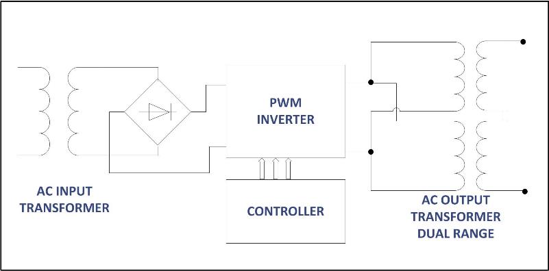
The vast majority of available AC power source designs are based on pulse-width modulated control circuits and the use of low frequency transformers to provide isolation between input and output of the AC power source.
Click image to enlarge
Figure 2‑1: Basic Conventional (Analog) Power Source Topology
These PWM design generally use analog control circuits to provide output regulation, current limit functions and frequency conversion functions. While this is a proven design dating back to the early 80’s, it is fraught with a series of drawbacks. Enter new all-digital topologies.
Digital Power Conversion
The higher PWM switching speeds required to support the wide output frequency range of an AC source, often higher than 30 kHz have made it difficult to use digital signal processors to provide all control functions. With the recent advances in DSP technologies, a full digital implementation of an AC power source design, supporting these switching frequencies, is now feasible.
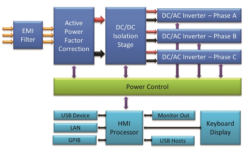
A good example of this is the new Pacific Power AFX series which uses a three stage, all digital power converter design that eliminates both AC input and output transformers and allows a power density five times higher than similar contemporary products and a fourfold reduction in weight.
The block diagram below should the top level topology of this three stage converter design. The three inverters have direct coupled outputs and are capable of supporting any combination of AC and DC voltage up to the limit of the voltage range.
All power stages are synchronized internally so frequency and phase angles are precisely controllable.
Click image to enlarge
Figure 3‑1: All Digital Power Source Topology
Important EUT Protection Functions
Programmable power sources provide the design or test engineer with a wide range of capabilities and functions for design verification and performance testing.
Some of the capabilities are critical, in particular protection of the equipment under test against excessive current, power or voltage that could result in permanent damage of the EUT. During prototype development, the loss of a prototype can result in serious schedule delays and thus cost. Some of these protection mechanisms, like programmable RMS current limit, are common in programmable power sources but others are quite new.
1.1 RMS and DC Current limiting
This is the most common protection mechanism available on AC sources and DC power supplies alike. Load current is monitored continuously and any current level that exceeds a preset user determined max. RMS or DC current level results in one of the actions listed below:
1. The output is turned off (Constant Voltage Trip mode) protecting the load from any damage.
2. The output voltage is reduced to maintain the load current at or below the protection limit current value. (Constant Current mode)
The mode, CV or CC, is set by the user. In the latter mode (CC), the power source acts like a pseudo current source by regulation the current indirectly through the output voltage setting.
1.2 Power Limiting
Current protection mode, as described above, works well when the equipment under test has a fairly narrow AC input voltage operating range, for example 115V ± 10%. Many of today’s AC powered products use a universal, wide input voltage range of 85V to 240V. When developing or testing this type of universal input power stage, a current limit function will not be as useful. For the EUT to be tested over its entire voltage input range, the current limit must be set high enough to support max. input power at the lowest input voltage (e.g. 85V – 10% = 76.5Vin). If anything goes wrong in the power stage when operating at higher input voltages, this current limit would allow almost 3½ times the nominal power to be drawn for the AC power source (265/76.5 = 3.46 x). Such an excessive power overload can easily damage or destroy the EUT.
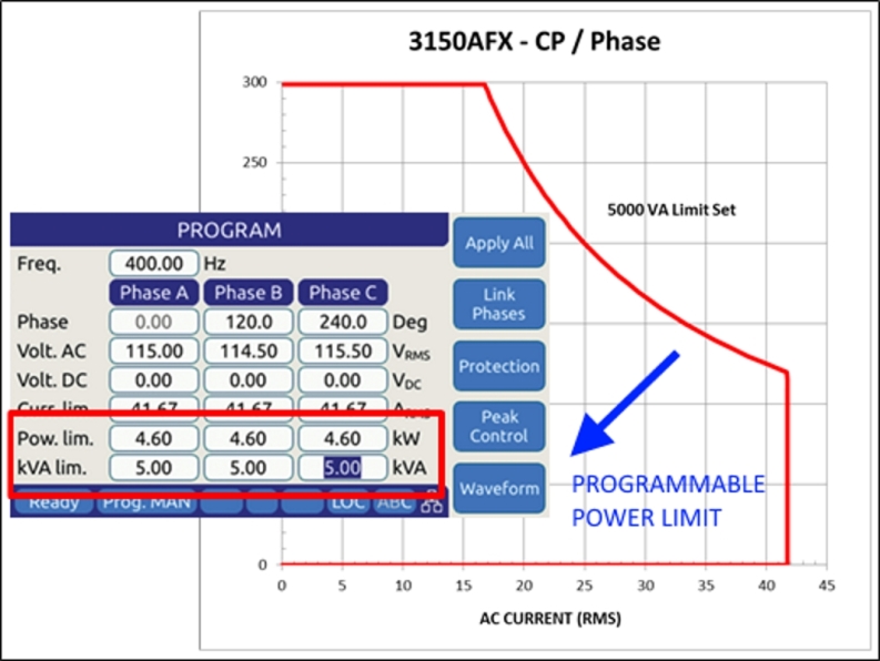
For these types of universal input voltage range power stages, it is critical that the power source has a programmable power protection mode as well as a CC or CV current mode. Power protection allows the max. VA or True Power (or both ) to be specified. This protection limit will engage regardless of the voltage or current operating levels.
The graph below illustrates the effect of adjust one or both power level limits on the output Voltage and current profile of the AC source.
Click image to enlarge
Figure 4‑1: Programmable Power Limit
1.3 Peak current limiting
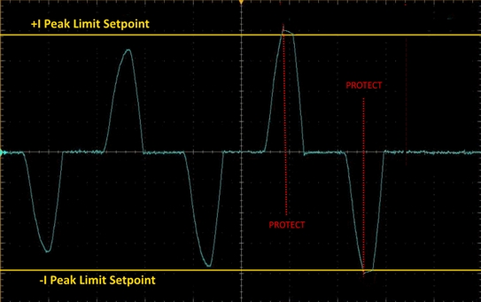
While RMS current limiting protects against excessive current flow, it is too slow to react to catastrophic events that can occur in a design, especially during its early design stages. The AFX Series offers a unique programmable peak current function that allows the user to control what maximum peak current level is acceptable. This protection mode operates on a switching-cycle by switching-cycle basis and responds in micro-seconds. It clamps the peak current to the pre-set limit potentially preventing serious damage to a prototype. Since early prototypes are often limited in numbers, this can avoid setting back engineering development schedules by days or weeks.
This protection mode is illustrated inFigure 4‑2below. As the current waveform peaks exceed the user defined threshold, the output inverter power devices are turn off to keep the peak current from rising further.
Click image to enlarge
Figure 4‑2: Peak Current Limiting Engaged
Constant Power Wide Output Voltage Range
While most AC power sources have dual voltage range to allow more current to be delivered at lower voltage, this is not always practical when dealing with wide input voltage range designs mentioned earlier. Switching between a high and low voltage range invariably requires that the output is turned off briefly to reconfigure the AC power source’s output configuration. This results in momentary power loss to the EUT which often will need to be re-booted.
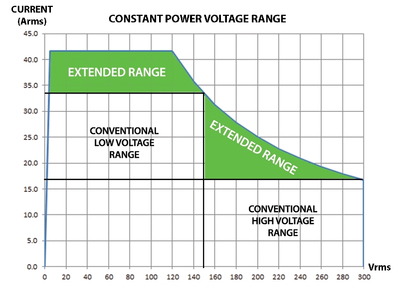
Such problems can be avoided by using a direct coupled, single amplifier per phase design with a constant power mode 300V rms single range output, all switching and reconfiguration has been eliminated. The AFX uses this approach. The resulting available current as a function of output voltage is shown in Figure 5‑1.

Click image to enlarge
Figure 5 1: Single, constant power voltage range
The additional operating areas are clearly visible if we overlay the V-I profile of a conventional dual voltage range AC source with that of the AFX Series as is done in Figure 5‑2. The additional operating area allows for full power operation over the widest possible voltage range.
Click image to enlarge
Figure 5‑2: Extended available useable range shown in green
User Interface
Having an intuitive user interface on any piece of test equipment is helpful for the user. Good examples of this are front panel touch-screen color LCD displays with simple menu operation and function or soft keys, all standard on the AFX. But on the latest designs, additional ways to interact with your test equipment are available as well.
1.4 Browser Interface
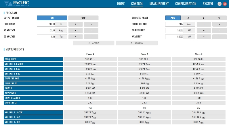
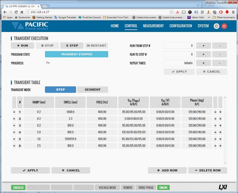
With the growing popularity of LAN interfaces and in particular LXI compliance for test equipment, new ways to access test equipment are available to the end-user now. An LXI compliant product will have a built in web interface allowing any browser to be used to monitor and control operation. The AFX expands on this with several additional browser pages for loading and displaying custom waveforms, setting up complex transient sequences and logging measurement data. No special software or instrument drivers are required for these capabilities as the web server is embedded in the product.
Click image to enlarge
Figure 6‑1: Program Control + Measurements and Transients Browser Screens
1.5 LAN Access Control is key
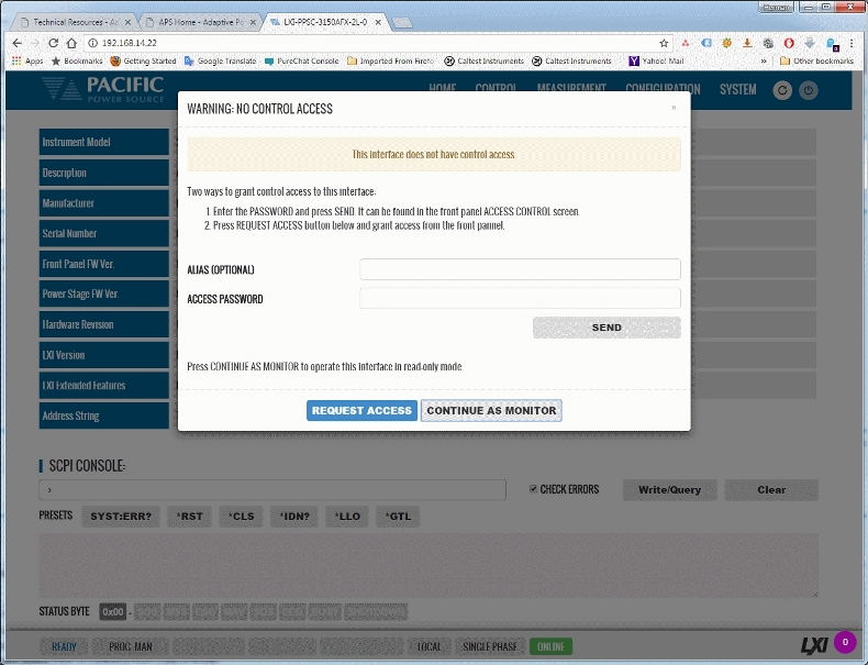
This LAN access allows the user to access his instruments from anywhere in world if needed. Of course, in the case of a programmable AC power source, security measures are critical as unauthorized access or access while others are working with or near the equipment can be potentially dangerous. Always check on the availability of security measures on LAN accessible power supplies or source with higher voltage output capability.
Click image to enlarge
Figure 6‑2: LAN Access Control Browser screen
1.6 Touch Screen Interface
Adding an external large touch screen monitors is another example of user interfacing that goes beyond regular test equipment. This allows front panel control or monitoring test data from across a lab or production floor.
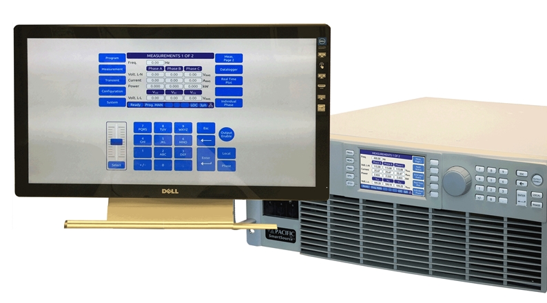
Click image to enlarge
Figure 6‑3: External Touch Screen Control
Green Power
As test equipment is often left on 24/7, energy savings features can save valuable resources as well as extend the life of the equipment itself. This is especially important for higher power models that can consume 100’s of Watts by just being turned on, even when not in actual use.
Modern designs like the AFX Series offer several energy savings modes that cause the unit to turn off its output inverters while remaining in standby mode so output power can be applied almost immediately if needed. A second level can be selected which completely powers down of three power stages and place the unit is a sleep mode consuming almost no power at all.
Not only does this save energy, expected life span of the power source is increased as all switching stages are dormant during this time. An additional bonus is whisper quiet operation during periods the output is off.
Conclusion
There are many factors that affect the suitability of a programmable AC or DC power source to an end-user’s application. Understanding the various functions and capabilities is important when making a selection. The more information you can share with the test equipment vendor, the better they will be able to steer you in the best direction to help you maximize your return on investment.


