Considerations When Selecting a Power Supply for Test Equipment

A guide to choosing the right power supply to use for test and measurement equipment designs
When choosing a power supply, if an engineer had only to consider volts and amps, cooling requirements, size, and regulatory certifications, their job would be easy as there are many available options from which to choose. However, designers of test and measurement equipment must consider other important parameters. Electrical noise, in its many forms, is a major concern because the speed and accuracy of the equipment rests greatly on the ability to minimize noise and keep it away from the sensitive electronics which sample and report the data that the equipment is designed to measure. Also important is the environment where the equipment can be used.
Noise
Electrical noise can be either differential mode (across power or signal lines) or common mode (between a power or signal line and a common ground) noise.
Radiated noise is a form of electromagnetic interference (EMI) transmitted through the air by cables and components with AC voltages or currents. The radiated coupling can be very local; for example, between a transformer and a nearby wire or PCB trace, and can become conducted noise.
Differential mode noise (aka ripple and noise) can range from a few microvolts in linear type power supplies, up to hundreds of millivolts in switching types. The values for the levels of this noise are normally specified by the manufacturers in both rms and pk-pk, although the pk-pk noise is generally 10 times higher than the rms noise and is potentially more troublesome to sensitive electronic circuits. Mitigation of the effects of this type of noise requires additional filtering, but since this noise is known when choosing the power supply, the effort required to minimize it is relatively easy.
Common mode noise
Common mode noise (between power or signal lines and ground) on the output of a power supply is often overlooked and rarely specified on power supply datasheets. This may be due to lack of knowledge by power supply manufacturers of its impact on product performance, or that it may not be an issue for the types of applications that they target with their products. The power supply output, in some applications, is often shorted to earth or chassis in the end application. In this case, the common mode noise will likely not be an issue.
However, it can be instructive to know and understand the common mode currents that flow in the circuit while making their way to ground. If the output of the power supply is connected to chassis/earth ground somewhere on the load board (electronics circuitry), there can be common mode currents flowing through the board. In addition, if the PCB layout is not done properly, the current can flow through sensitive parts of the circuitry and cause it to malfunction.
All switching power supplies will have some level of common mode noise, the extent of which depends on many factors including power supply topology, filter designs and input-to-output isolation. Since most power supply manufacturers do not typically specify the common mode noise performance in their documentation, the equipment designers are left in the dark when it comes to the common mode noise they will need to deal with. Power supplies that address common mode noise by minimizing it to practical levels, and also characterize the common mode noise profile of the units are worth serious consideration. Such power supplies will allow test equipment design engineers to determine the potential effects of this noise before spending hours or days characterizing this themselves.
Emissions
Emissions, both radiated and conducted, are also a major concern when integrating a power supply into test and measurement equipment. Test equipment, like many other types of applications, needs to comply with certain levels of EMI. Both radiated emissions (RE) and conducted emissions (CE) need to be within either class A or class B of CISPR22/EN55022/FCC Part 15, depending on where the end equipment is being used. Open frame power supplies typically meet class B for CE, and class A for RE.
Power supplies are normally tested with resistive loads when certifying their performance to these standards. This sometimes presents a challenge to equipment designers in that once the power supply is integrated with the test equipment, the EMI profile will typically change, as other factors (cabling, grounding, etc.) can change the overall system performance to these standards. A power supply that is designed to meet these standards with some level of margin gives test equipment designers a better chance of maintaining compliance in their equipment. This minimizes development time and potential material cost to make the end system compliant.
Environment
Test equipment operates in many environments – production lines in factories around the world (both testing other products, and in the factories building the test equipment itself), design engineering labs, research labs, etc. Many remote environments present different challenges to the equipment designer, as the equipment must operate continuously and reliably in all geographies and environments the equipment is to be used. Unstable power sources, noisy (electromagnetic) environments, etc., can affect the operation of a power supply, and therefore, the system in which it is used.
In order to provide the best protection against external influences, compliance to the highest levels of Electromagnetic Compatibility (EMC) standards is needed. The typical standards are IEC61000-4-x, with the “x” being one of various numbers denoting a specific section of the standard. Most power supplies comply with various levels of certain sections of the IEC61000 standard, the following being the typical (See figure 1).
IEC 61000-4-2 defines levels of Electrostatic Discharge (ESD) protection, using two different testing methodologies:
· Contact discharge involves discharging an ESD pulse directly from the ESD test gun that is touching the Device Under Test (DUT).
· Air discharge, where an ESD test gun is brought close to the DUT until a discharge occurs.
Table 1:
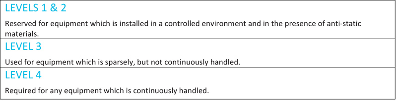
Click image to enlarge
For test equipment which comes into contact with operators regularly, level 4 (8kV contact, 15kV air) would provide the best protection for all environments.
IEC61000-4-5 relates to the immunity requirements, test methods, and range of recommended test levels for equipment to unidirectional surges caused by over-voltages from switching and lightning transients. Several test levels are defined which relate to different environment and installation conditions. These requirements are developed for and are applicable to all types of electrical and electronic equipment, including test equipment. Areas around the world where unstable and unconditioned AC sources provide the power for test equipment – in labs, in factories, etc. will potentially subject the equipment to various surges that could potentially shut down, or even damage the equipment. Power supplies that are compliant to level 4 (4kV), will provide superior protection against high levels (2kV line-line, 4kV line-GND) of input surges.
IEC61000-4-11 defines the immunity test methods and range of preferred test levels for electrical and electronic equipment connected to low-voltage power supply networks for voltage dips, short interruptions, and voltage variations. This standard applies to electrical and electronic equipment having a rated input current not exceeding 16A per phase, for connection to 50Hz or 60Hz AC networks.
The standard describes three different tests:
1. Voltage dips are defined as sudden reduction in voltage to lower voltages for a short period of time, followed by recovery to the original voltage.
2. Short interruptions are defined as a disappearance of AC voltage for a short period of time, typically not exceeding one minute, followed by recovery to the original voltage. Short interruptions can be considered as voltage dips to zero volts.
3. Voltage variations are gradual changes of the supply voltage to a higher or lower value than the rated voltage. The duration can be short or long.
The ability for a power supply to continue to operate during dips in input (mains) voltage and interruptions ensures that the equipment it is used in will also continue to function through these anomalies, minimizing any downtime. These voltage dips and interruptions vary in magnitude and length (See figure 2).
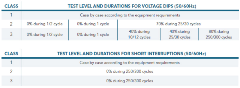
Click image to enlarge
Figure 2: EN61000—4-11 Test Level and Durations for Voltage Dips and Short Interruptions
Power supplies that have higher levels of hold-up time perform the best when subjected to these voltage dips and interruptions. They are able to ride through them, without output voltage deviation. Power supplies with short hold-up times will typically shut down and restart during these dips. The equipment designer will need to understand the operational nature of the equipment to determine if an intermittent shutdown is acceptable.
Engineers designing test equipment have many challenges to consider when choosing a power supply for use in their end equipment. External influences on the systems and circuits that perform the data sampling and measurement tasks in test equipment can adversely affect the function of those circuits, requiring equipment designers to spend a great amount of their development shielding these circuits from those influences.
SL Power’s TU425 series models (See figure 3) were designed with these challenges in mind. The enhanced performance of these models to output noise, EMI, and EMC requirements will make the test equipment designer’s development effort easier.
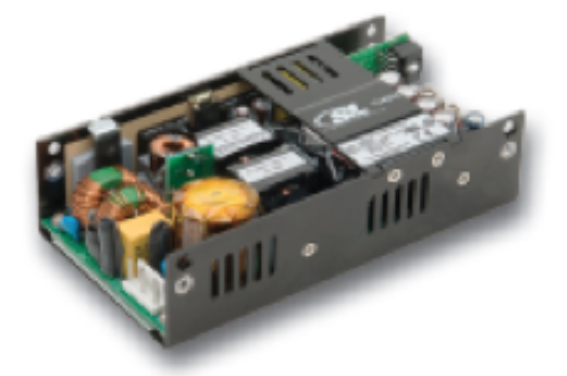
Click image to enlarge
Figure 3: SL Power’s TU425 AC/DC 425 watt power supply is designed with the highest level EMC and EMI protection
SL Power Electronics


