Considerations for energy storage, illumination & communications
Figure 1: Typical Solar Panel Output Current & Power vs. Output Voltage Curve
The influence of clouds, trees, dirt, on the solar cell panel and the rotation of the sun causes problematic fluctuations in the amount power generation. Consistent with the movement towards more environmentally friendly solutions, self-sustaining solar-powered infrastructure is starting to be deployed around the world. To improve customer service, convenience and safety, public service stations with nighttime illumination and wireless communications capabilities are being deployed in increasing numbers. Illuminated bus stops with real-time arrival time information are appearing in North America. Solar-powered ticket kiosks are appearing in Europe. These units may also be deployed in outlying areas where electrical and wired communications infrastructure may not be cost effective to build. In both cases the units must be able to wirelessly communicate to perform their respective functions. The proof of concept is out there, but how can we optimize the power network within the system to make the most efficient use of available sunlight for maximum up time with minimized costs? Solar Cell Operating Characteristics The amount of energy produced by a panel of solar cells is proportional to the total amount of light received. The influence of clouds, trees, dirt, surface area of the solar cell panel and the rotation of the sun can cause dramatic fluctuations in the amount of light available for power generation. Combined with solar cells' characteristically high source impedance, a load that attempts to pull a relatively large constant current may encounter periods of time where there is no power delivery to the load, the charger and battery in most cases. Therefore, a circuit must be applied to carefully control the current and correspondingly maximize power delivered from the solar cells to the charging unit. The typical output current and output voltage characteristic for solar cell panels is shown in Figure 1. An interesting trend emerges in that regardless of the lighting conditions for a given panel, the maximum output power will be delivered when the output voltage is at a relatively constant voltage, VMPP. The voltage VMPP may be found by reviewing the technical documentation for the solar cell panel of interest. At the same time, a good practice may be to verify the VMPP figure independently, creating the I-V curves like the one shown in Figure 1 using successively increasing or decreasing loads under the same illumination conditions that may be easily created by facing the panel at various angles to the sun. Viewing the performance curve from a real solar cell panel, the importance of extracting power from a solar cell at VMPP cannot be understated.
The data in Figure 2 was gathered within a minute period with the panel aimed directly at the sun under clear skies at our Milpitas, California campus using an automated load box. As indicated by the graph, an uncontrolled load could cause the net output power to vary anywhere from under 2 Watts to 47 Watts in direct sunlight. If it were possible to maintain the output voltage of the panel constant at approximately 13V, we could be assured that the maximum amount of power is available to the load. But how could this task be accomplished? Optimizing Solar Cell Power Energy generation costs from solar are still higher than that of traditional sources such as coal and natural gas due in part to the cost of the solar cells. While the cost per Watt figure is decreasing, a July 2011 report by SolarBuzz.com indicated solar cell pricing was in the range of €0.96 - €2.54 per Watt of peak generating capacity depending on volume and technology. As stated previously, non-ideal sunlight conditions often prevent the panel from operating at peak generating capacity. Moreover, any potential impedance mismatch between the solar cell and the load (operation at other than VMPP) must be considered for the application and factored into the amount of solar generating capacity to design into the system. As the mismatch is reduced so does the solar panel size and cost while achieving the same power output.
A convenient approach to reduce impedance mismatch is achieved by employing a Maximum Peak Power Tracking (MPPT) circuit between the output of the solar cell panel and the load. In particular, this circuit varies the current load to maintain the voltage at VMPP. The circuit may be built with discretes using a myriad of components or integrated within a device like the LTM8062 switching μModule battery charger. The MPPT offered by the LTM®8062 is a simple solution adjustable by a single resistor to ensure maximum power is delivered to the load under widely varying illumination conditions. The effectiveness of the MPPT circuit may be best demonstrated by comparing the output power of two identical setups using a Solec S-70C panel with MPPT enabled and MPPT disabled, the latter implemented by pulling the VINREG pin of the LTM8062 to VIN. The test circuit schematic is presented in Figure 3.
Energy Storage: Circuit Comparison Components & Setup The LTM8062 is a highly efficient integrated constant current, constant voltage (CC/CV) step-down switching battery charger solution accepting a 4.95V to 32V operating input voltage range. The user-programmable battery float voltage up to 18.8V allows it to support a battery stack consisting of up to 8-cells of sealed lead acid, 4-cells of Li-Ion or Li-poly, or 5-cells of LiFePO4. The integrated MPPT circuit saves a great deal of design complexity as compared to a discrete implementation suggested by other industry members consisting of more than ten components. As mentioned previously, the circuit drives the LTM8062 to automatically reduce or increase the battery charge current up to 2A to source the maximum output power from the solar cell(s). In the most basic application, the LTM8062 requires just 3 external components for operation in comparison to anywhere from 15 to 30 components for a traditional discrete implementation. The charging process terminates after a user adjustable time period expires or charge current falls to a minimum threshold (200mA) with a battery voltage accuracy of 1.5% over temperature. Two open-collector status indicators CHRG and FAULT are compatible for use with LEDs for visual cues. The CHRG indicator signals when the device is charging the battery. The FAULT indicator signals if the battery has not responded to charge within a fixed time period or an over temperature condition occurred using the optional NTC thermistor input pin. The LTM8062 will automatically re-charge the battery should the voltage drop below 2.5% of the programmed float voltage or a new battery has been inserted. An internal blocking diode is available to prevent reverse current from the battery back to the source when the solar cell voltage collapses at night. For increased charge current, the outputs of multiple LTM8062s may be paralleled together. In this arrangement the modules can share a single pair of feedback resistors as shown in Figure 3. Three LTM8062 modules were connected in parallel for a maximum charge current of 6A �7.5% in the constant current charging state. The charge termination voltage was set at 8.4V. The Solec International S-70C is a monocrystalline solar cell panel rated for 70W peak output power. Empirical measurements under varying light conditions determined the maximum power voltage to be 13V although the label indicated a VMPP figure of 17V. Still, it displays the typical performance characterics of solar cell panels. The panel was positioned to lie parallel to the ground for all measurements to model a flat roof. Since the initial charge state of the battery in a real world application is highly variable depending on the system usage, size of the battery, and sky conditions on prior days among other factors, an electronic load was used to simulate a maximum power draw from the solar panel approximately at the transition between constant current and constant voltage charge regions. By challenging both circuits at this operating point, we can be certain the circuit will support all other events in the charge cycle. With a 8.4V charge termination voltage corresponding to a two-cell Li-Ion stack, the electronic load was asked to pull up to 6A from the three LTM8062 charger modules in parallel while maintaining a voltage of approximately 8V.
Maximum Peak Power Tracking Effectiveness Measurements were taken with the MPPT circuit enabled and disabled throughout the day outside our Milpitas, California campus on a summer day. Those familiar with San Francisco summer patterns will be familiar with typically overcast mornings becoming perfectly clear by afternoon. This turned out to be the case for our experiment performed on a July day. Measurements were taken during normal business hours, although a real application would potentially have hours of additional light available before and after the data was gathered. Figure 4 shows the effective load current and power delivered to the electronic load simulating our 8.4V Li-Ion battery at near maximum power draw throughout the day as well as the atmospheric conditions that were perfectly clear except where noted.
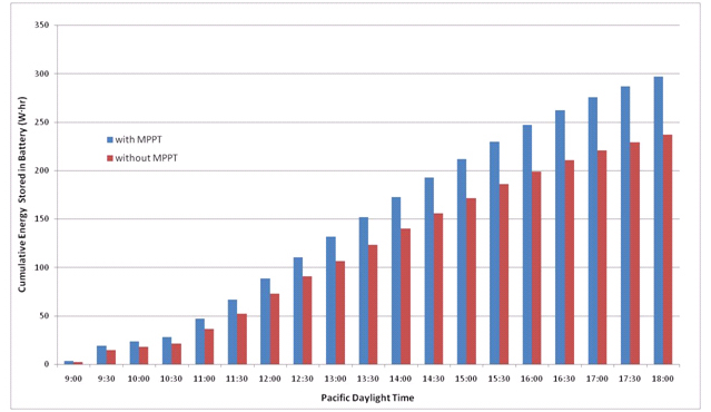
The current and power delivered to the simulated battery cell is dramatically higher with the MPPT circuit active compared to the circuit inactive. The current to the load showed a 20% - 40% improvement with the exception of the noon period where the LTM8062's internal maximum charge current limit was reached when MPPT was enabled. Separating the battery charger and load from the circuit for a moment, an active MPPT circuit extracts 18% to 42% more power from the solar cell panel than with the circuit inactive. In general, the more dramatic improvement tends to be at lower light levels during the morning and evening hours. The additional energy delivered to the load over the 9 hour period would have been approximately 240W�hr without the MPPT circuit and 300W�hr with MPPT enabled (Figure 5), an improvement of 25%. Accordingly, a 100W solar cell panel system with an MPPT enabled at the load would generate equivalent power to a 125W solar system without MPPT. Using a solar cell panel market price of €1 - €2.54 per Watt, the potential cost savings would be equivalent to €25 - €63.5.
Reliable Energy Efficient Illumination With the maximum output power now efficiently stored in the battery, the most reliable and efficient way to provide nighttime illumination today is with LEDs. The new San Francisco City bus stops being introduced consume 74.4 Watts with LEDs as compared to their fluorescent bulb illuminated predecessors which consume 336 watts. Cost of ownership is also reduced as LEDs last ten times longer than their fluorescent counterparts. Furthermore, LEDs require DC power for operation fitting perfectly with the DC power available from the solar cells and batteries. Fluorescent bulbs require an AC voltage typically in the range of 200V - 1500kV for operation requiring a costly and complex driver when operating from a DC power supply. The relatively high voltage AC power supply required by fluorescent bulbs can also become a source of interference with potential wireless communications described in the next section. Mirroring the LTM8062 in efficiency, reliability, and convenience the LTM8042 constant current LED driver presents a worthwhile solution for illumination needs.
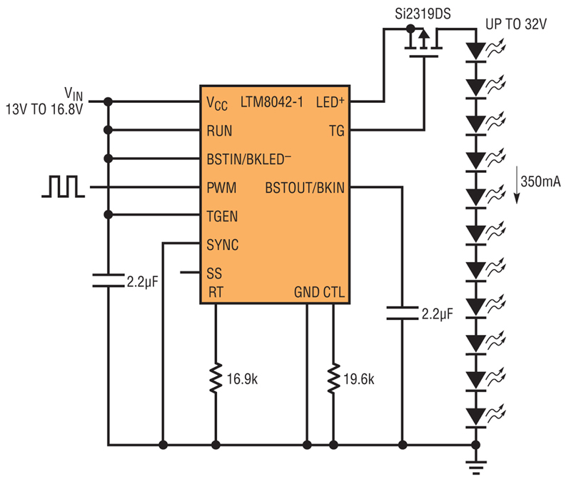
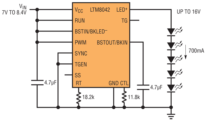
Whether a Boost, Buck or even Buck-Boost operation is required, the LTM8042 and LTM8042-1 are easily configured to deliver a constant current up to 1A and 350mA respectively. In this experiment, the simulated 8.4V Li-Ion battery pack would deliver most of its energy at approximately 7V, allowing the LTM8042 support a 700mA LED string up to 16V for a luminous flux of 1300 lumens using neutral white XLAMP XM-L LEDs by Cree. With the same battery pack, the LTM8042-1 could drive a 24V LED string at up to 350mA delivering a luminous flux of 1040 lumens using neutral white Luxeon Rebel ES LEDs by Lumileds. If two solar panels were stacked in series to raise the VMPP to 26V and the battery stack increased to 16.8V, a luminous flux up to 2880 lumens could be achieved with the XLamp XM-L LEDs or 1430 lumens with Luxeon Rebel ES at 350mA. Both the LTM8042 and LTM8042-1 form a complete LED driver solution operating from an input voltage of 3V to 30V, requiring as few as 3 external components. To save power during dusk and dawn hours, the LTM8042 supports two dimming methods. Up to a 3000:1 dimming ratio may be achieved using the PWM input demonstrated in Figure 6b. Analog dimming may be applied using a resistor or voltage. The switching frequency is adjustable from 250kHz to 2MHz and may be synchronized to an external clock up to 2.5MHz for noise sensitive applications. Clear Communication is Key Whether it's a Wi-Fi, HSPA, LTE or other wireless standard, communication systems are consuming less power and the supporting service area constantly increasing in size. Wireless communication is an easy addition to public service infrastructure. Public transportation stops communicate real time service updates to their passengers. Ticket kiosks are processing electronic payments for passengers. Solar-powered sensors are starting to be embedded in the streets of major cities to identify open parking spots to drivers and thereby relieve traffic congestion. The ability to clearly communicate information from and/or to the system is key, particularly wireless communication if the system is off the grid where traditional wired communication infrastructure may not exist. Low noise radiated noise solutions are important in wireless communications for improved signal reception and transmission. Linear Technology offers eight simple and easy to use DC/DC step-down μModule regulator products which are certified to meet the EN55022 Class B radiated EMI (electromagnetic interference) specification with the highest output power ratings in the industry. Tests were performed using the standard demonstration board whose Gerber files are available to all design engineers. Their EMI performance is proven by third-party independent tests reports which may be reviewed online. Linear Technology's line of EN55022 Class B certified step-down μModule regulators accept operating input voltages up to 36V and output currents up to 8A with support for accurate output current sharing among multiple modules increasing output current capability to over 32A. Engineers designing wireless communications networks with high uptime requirements have already found them to be a valuable tool. Conclusion The benefits of self-powered intelligent urban infrastructure are far reaching. The technology exists today to make it possible; however optimization is required to make it practical. The Maximum Peak Power Tracking feature of the LTM8062 μModule battery charger delivers up to a 40% increase in the amount of power extracted from a solar cell panel in a compact, convenient reliable and efficient solution. Over the course of one day, a 25% improvement in energy was achieved which could potentially save €25 - €63.5 in solar panel costs per 100W of peak generating capacity at current prices. Compact and efficient power modules exist in a compact form factor for LED lighting and noise sensitive wireless communications to enhance system functionality. In combination with advancements in battery storage technology, solar cell and LED efficiency, more urban and even remote environments can now be a cost effective solution for self-powered intelligent public infrastructure with the assistance of an efficient, reliable and convenient battery charger with Maximum Peak Power Tracking. www.linear.com