Detecting IT Power System Resistive and Capacitive Faults with Insulation Monitoring Technology
Understanding Fault Detection Methods and Potential Challenges
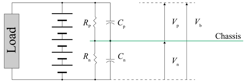
Figure 1: Generalized IT power system
While sales of electric vehicles in the U.S. have underperformed their once-lofty expectations, their continued expansion and maturity has pushed regulators toward greater specificity around the various safety standards which surround them and the corresponding charging infrastructure.
One area which remains ripe for continued regulatory change is insulation monitoring (also known as isolation monitoring) for both electric vehicles as well as the charging stations required to charge them.
Electrical isolation is accomplished in a high voltage system by using non-conducting barriers such as insulation on cables, plastic housings on components and physical distance. Isolation failure means that there is a resistive path that is allowing excessive current to flow where it should not. Quickly determining when a failure happens is critical, as it poses an electrocution risk to human beings.
In high voltage systems, isolation is often expressed in ohms/volt, where the isolation resistance is divided by the maximum system voltage. Therefore, the amount of resistance required increases with overall system voltage. The typical industry standard for a minimum isolation resistance is 100 ohms/volt.
What is Insulation Monitoring?
As their name implies, insulation monitors monitor the resistance between the floating high voltage system and the chassis of the vehicle or frame of a charging station. It essentially ensures that someone can safely touch the door of an EV or the handle of a charging station without being exposed to high voltage. This continuous monitoring is essential for the safety of such systems as even a single fault can generate hazards to personnel in contact with these systems.
In a standard IT power system, the resistive connections between the terminals of the power source and the chassis can be mathematically combined as the “isolation resistances”, representing the parallel combination of all resistive paths from the power source terminals to the chassis. These are shown as Rp and Rn in Figure 1. The voltages Vp and Vn are shown each to be equal to half of the battery voltage, which will be the case during normal operation of the system with proper isolation.
Within EVs and charging stations, high frequency switching of components within the system can create electromagnetic interference and high frequency disturbances on the power rails, also known as common mode noise. To meet the relevant electromagnetic interference limits imposed by standards - ensuring non-interference between devices and systems – engineers typically integrate Y-capacitors to suppress that interference.
Total capacitance in an electric vehicle or charging station is determined by both the intentionally designed Y-capacitors and the parasitic capacitance formed by metal housings, cooling systems and related structures. Changes in the value of these parasitic capacitances can be used as one of the indications of the status of operating conditions of such systems including those related to cooling and electronics measurement. The sum of the intentional Y-capacitance between the source terminals and ground and parasitic capacitance are shown as Cp and Cn in Figure 1.
Summarizing complex EV and charging station architectures in this manner is helpful in understanding the parameters that the IMD is responsible for monitoring.
Types of Faults in IT Power Systems
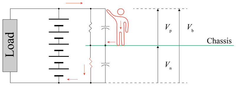
A resistive fault occurs when there is a resistive path that is allowing excessive current to flow where it should not. If a resistive fault occurs (pushing one of the isolation resistances below 100 ohms/volt) there is the potential for a hazard if a person contacts the terminal opposite the failed resistor. In this situation, they would close the circuit and allow for a potentially deadly amount of current to flow through their body (Figure 2). This is known as an “asymmetrical” fault. It is also possible that resistive failures occur on both the positive and negative sides of the circuit simultaneously, which is known as a “symmetrical” or “double” isolation fault.
Click image to enlarge
Figure 2: Asymmetrical resistive fault resulting in dangerous condition for human beings
Resistive faults can be caused by several factors. Some of the more common causes include:
- Vehicle Crash – The large impact imposed from a crash could cause several resistive faults. These include deformation of the vehicle’s frame, damage to high voltage architecture or internal battery components coming loose.
- Faulty High Voltage Connectors – Incorrect installation or breakdown of physical barriers within the connectors over time or from misuse can create a leak path for current that needs to be detected.
- Human Error – When servicing a vehicle or charging station, a part installed incorrectly or not re-installed at all can lead to unintended current flow.
- Corrosion – Gradual deterioration of isolation mounts or fraying of HV cables over time.
- Contamination – A foreign object of a conductive material can create a connection between the high voltage system and the chassis of the vehicle or charging station. This connection can also be made by foreign material such as condensation, smoke, or battery leakage.
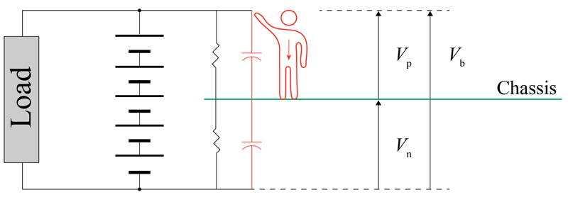
In addition to resistive faults, there is also the potential for a capacitive fault in the system. While not yet required to be monitored by international standards, this hazard can be caused by excessive energy stored in the system’s capacitors. Failures within an electrical sub-system, coolant leakage or incorrect servicing may alter the originally designed capacitance values. In this case energy discharged through a person’s body can create a hazardous event as shown in Figure 3. The stored energy and, subsequently, the severity of the hazard increases exponentially with the voltage of the system. For instance, going from a 400 V to an 800 V battery quadruples the energy stored in its Y-capacitors.
Click image to enlarge
Figure 3: Capacitive fault condition in floating high voltage system
Fault Detection Methods
There are several strategies in use today to monitor the isolation status of ungrounded high-voltage systems. Some are more capable than others, and technology selection is based on the system designer’s balance of cost and capability.
Voltage Measurement Method – This is the simplest approach to detect an isolation fault. In this method, voltage measurements between each power pole and the chassis are used to detect an isolation fault due to an imbalance between the two voltages Vp and Vn. However, because this method will not detect symmetrical faults, its effectiveness is limited. In addition, this method is susceptible to common mode noise and cannot detect capacitive faults.
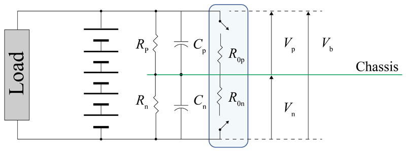
Resistance Switching Method - In this approach, known resistors are inserted in parallel to the isolation resistances already present in the system (Rp and Rn). These are shown in Figure 4 and are labeled as R0p and R0n and are connected to the system via switches controlled by the IMD. These resistors are alternatively inserted into the system at periodic intervals to create small disturbances. These disturbances allow the IMD to measure the resultant small changes in voltage and determine overall system resistance. The core challenge of this approach is that the resistor inserted into the system generally needs to be within 100 to 500 Ω/V to reach accuracy and performance targets. This is exactly the range in which the isolation of the system becomes hazardous, which means that during the measurement period (when one of the resistors is inserted) the system becomes potentially unsafe. It also does not have the ability to measure system capacitance and requires a degree of overall system voltage stability to attain accurate measurements. When implemented correctly however, this approach can be a cost-effective way to monitor insulation and is used in many applications today.
Click image to enlarge
Figure 4: Resistance Switching Method Schematic
Signal Injection Method – As indicated by the name, in this method the necessary disturbance in the system is created by injecting small voltages into the positive and negative branches of the circuit. This excitation voltage is shown in Figure 5 as Vep and Ven. The resultant response of the system is a function of the overall system load and changes in the system’s response can be used to determine its status. This approach allows for the detection of both asymmetric and symmetric faults without introducing a potentially hazardous situation during measurement as seen in the resistance switching method. Other advantages include being able to measure system resistance while the battery is not connected and robustness to variations in battery voltage. Challenges include the costs associated with the signal generation hardware and developing the firmware to decipher the system’s response to a resultant resistance value.

Click image to enlarge
Figure 5: Signal Injection Method Schematic
Sensata’s Patented Signal Injection Method
As mentioned in the description of the resistance switching method, accurately measuring resistance in an IT system is very difficult in a stable state. Therefore, a small disturbance is needed to generate a system response that can be measured on a consistent basis.
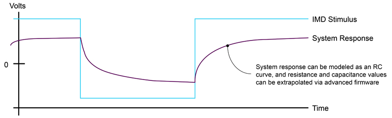
Like most IMDs that use the signal injection method, Sensata’s SIM family of IMDs creates this disturbance by injecting a small voltage through isolation resistors onto both the positive and negative high-voltage rails. The injection pulses alternate between the positive and negative rails at set time periods. How the voltage returns to the IMD is a function of the resistance and capacitance of the system and can be modeled as an RC curve. The duration and amplitude of these pulses can be adjusted to closely match the system voltage and overall capacitance for accurate modeling of the system’s representative RC curve.
Using a patented algorithm, Sensata’s SIM family of IMDs models this RC curve and extrapolates not only the resultant resistance of both the positive and negative sides of the system, but also the total capacitance of the system. The algorithm also outputs the live uncertainty of the measurements.
Click image to enlarge
Figure 6: Modeling system resistance and capacitance as an RC curve using advanced IMD firmware
Recall that one of the signal injection method’s key advantages is being able to determine the safety of the system without the presence of high voltage. (For example, before the main contactors are closed on an EV or before a charging cable is connected to a vehicle.) This is possible because this style of IMD can generate its own excitation voltage. Sensata’s SIM family of IMDs builds on this key advantage by also incorporating several other features:
- Identification of location of fault on positive or negative side of the high voltage system
- Capacitive fault monitoring and measurement of overall system capacitance
- Output of measurement uncertainty
Future IMD Regulations
As EVs and charging stations continue to evolve and increase power, regulations will continue to change to ensure the safety of these systems. IMDs will be required to be more accurate, respond faster and provide more information beyond just determining system resistance. Two areas primed for future regulation are capacitance monitoring and measurement times.
Megawatt charging and beyond will require large increases in system capacitance on both the charger and vehicle side to accommodate the increased power demands. This large capacitance combined with future charging voltages surpassing 1000V will generate a huge amount of stored energy that potentially will need to be monitored for safety. Being able to accurately measure this capacitance and quickly react if something is out of specification is a key piece of ensuring these systems remain safe operating at such high power levels.
In addition to more power, customers are always looking for faster charging times for their vehicles as well. When connecting a vehicle to a charging station, current regulations require the charging station IMD to determine the safety of the system before allowing the battery to be charged. This can take several seconds or minutes, especially if the IMD technology selected is slow and requires the system to be powered in order to determine its safety. Requiring IMDs to perform isolation checks quicker and without power on the system are a potential future addition to isolation monitoring specs.
Insulation monitoring technology is emerging as an interesting, innovative technical space that will continue to evolve as regulations mature and systems become more complex and powerful. Today. IMDs using the signal injection method are primed to meet any future regulations in these areas as the technology is flexible, scalable and is controlled by firmware capable of adapting to new demands and specifications. Ensuring everyone is safe around our high voltage systems will safeguard their continued growth and innovation as we pursue a more electrified world.


