What can it do for FPGAs, Processors and other loads?
An engineer designing with FPGAs or Processors often has to provide some serious amount of power at high efficiency over load. Not only must the rails be regulated correctly and not overheat, but additional functionality may be required.
Recent evaluation boards from Xilinx (ML605 and SP605) for Virtex-6 and Spartan-6 FPGAs use a Texas Instruments digital controller power scheme. From the myriad ways to provide point-of-load power, why does an engineer need the digital power option? This is the question addressed here.
A Digital POL Power Scheme
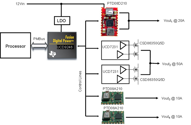
Figure 1 shows a multi-rail digital controller IC, UCD9246, connected to a variety of power stages. The controller regulates the output voltages via sampling voltages / currents, implementing digital control loops and outputting high-resolution PWM signals to the power stages. A power stage has the FET drivers, FETs, power inductor and capacitors. It also provides the current / voltage / temperature feedback signals for the controller.
Click image to enlarge
Figure 1: Digital POL Power Scheme
The Power Stage
The simplest way to implement the power stage is with a compact (15 x 28mm) digital power module like PTD08D210. It has two outputs that can be configured as 2 x 10A rails, or paralleled for a 1 x 20A rail. Another way to design a power stage is to use the digital FET driver UCD7232 (to release soon, similar to UCD7231) plus Texas Instruments very high efficiency “NexFET” MOSFETs, like the dual CSD86350Q5D or CSD86330Q3D.
Reasons to implement a voltage rail using the discrete ICs include (1) It is possible to convert from a lower input voltage – down to 2.2Vin (2) You can choose your own inductor and e.g. minimize its height. (3) You can design a rail with a particular output current to suit.
The Fusion GUI
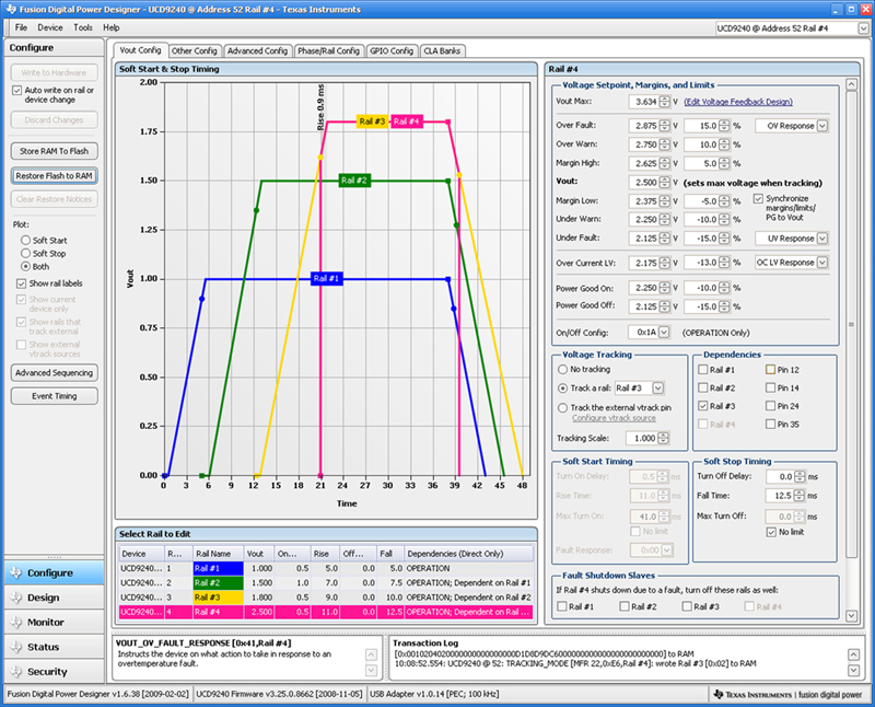
The Fusion Digital Power Designer™ GUI is the powerful, free-download, Texas Instruments software used to configure all aspects of the controller. The Vout Configuration window is shown in Figure 2, as an example. The graphical representation of the sequencing makes it easy to visualize what effect the numbers being entered for the parameters will have.
Click image to enlarge
Figure 2: Vout Configuration Window in the Fusion GUI
Evaluation Board
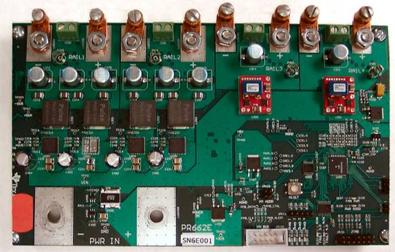
The UCD9246 evaluation board, Figure 3, shows how quickly it is possible for a designer to get up and running producing multiple high current rails. It connects to a PC and is configured using the Fusion GUI.
Click image to enlarge
Figure 3: UCD9246 Evaluation Board
9 Features of a Digital POL Solution
Ultimately, designers choose a particular solution over another one because of the cost-benefits, not because a solution is new or because it is “digital.” In this section the benefits of the UCD92xx digital power solution are examined and their relationship to the Fusion GUI explained.
(1) Sequencing of rails up / down. Frequently, there is a requirement for certain voltage rails to be present before others, particularly when powering an FPGA or processor. Even if there is not a requirement, there still may be a case for sequencing them to guarantee repeatability when the design goes to manufacture. Another good reason for using sequencing is to reduce inrush current.
The Fusion GUI easily allows setting the dependencies of each voltage rail upon other rails – you can set a voltage rail to start (or stop) after another has reached regulation or gone out of regulation.
(2)Monitoring and event-logging to non-volatile memory. The UCD92xx controller allows four levels to be set per rail – under/over voltage warning and under/over voltage fault. The controller can be set to take actions, such as turning off other rail(s), or automatically restarting, if a rail goes out of its User-defined regulation.
The current per phase is also monitored by the power stage and reported back, as is the input voltage and power-stage temperature – if a digital power stage module is used. Over/under current, over/under voltage, over temperature warnings and fault thresholds can all be set by the user.
(3)Parts count reduction. Using the digital power solution enables multi-rail, multi-phase power supplies controlled by one IC. Since timing is configured digitally, there are no timing caps or resistors. The compensation loops are in the digital domain, so there are no external passive components to set poles and zeros. The same IC also provides other features, such as the monitoring and sequencing functions.
(4)Digitally changing Vout & Vout Margining. A digital power solution has Vout for each rail under digital control, meaning the host processor can write a new value of Vout for a particular voltage rail over the PMBus interface to the digital controller. Some controllers in the UCD92xx family, such as the UCD9222 and UCD9224, also have a multi-bit VID (voltage identification) interface which allows the powered device to dynamically adjust the voltage being supplied to it.
Margining is the ability to change Vout up or down by a prescribed amount to test the robustness of the overall system design to the set-point tolerance of each rail and is fully supported by the controller.
(5)Paralleling of outputs for higher current and phase-shedding at light load.
It is often desirable to parallel multiple sets of MOSFET half-bridge and inductor circuits. At full load, where conduction losses dominate, the efficiency of the multi-phase converter is higher than a single phase solution. Another advantage of using multiple phases is to increase the surface area of the power conversion, which enables improved thermals and a lower profile solution. If the switching action of the phases is interleaved, then the effective switching frequency is increased and a reduction in output and input ripple voltage can be obtained, reducing capacitor count.
At light load, when switching losses become a bigger factor, the UCD92xx controller can be configured to automatically turn off unneeded power stages. This is called phase-shedding and increases light-load efficiency.
(6)Configure your own control loop compensation or use Autotune. Autotune is a powerful part of the Fusion GUI that designs the poles/zeros compensation for a modular or user-defined power stage. Non-linear control can be used. An example would be to reduce the gain during steady state conditions to minimize jitter noise on the output, but if the error increases past a certain level, then switch to a higher gain, to bring the converter’s output back to the set-point more quickly. This means Vout disturbances in response to load transients is minimized.
Auto-ID is another remarkable feature of the UCD9246, which injects a sine wave into the control loop and measures the system response at another point in the loop. This allows the UCD9246 to measures its own closed-loop transfer functions.
(7)Switching frequency synchronization. In some applications it is desirable to synchronize the switching frequencies across one or more controllers to a common clock input and this is supported by these controllers.
(8)Pre-bias start-up. “Pre-bias” refers to a pre-existing voltage on a non-enabled rail (e.g. the core voltage) that has been parasitically charged-up to some voltage via another voltage source. If not carefully managed, when the core voltage rail is enabled, a large current can flow through the synchronous MOSFET, destroying it.
To prevent this, the controller implements a closed-loop start-up function, using the pre-bias on Vout as an input to that function. As a result, when the voltage rail is enabled it ramps up seamlessly and monotonically.
(9)Supports last minute changes and new customer requirement spins with no hardware changes. Sometimes, last minute requirements or changes creep into the specification. Because more of the power scheme is under firmware control, the chances are greater that the amendments can be made without needing a board spin.
Conclusion
Digital POL power finds its niche in applications where their strong features are valued and helps engineers designing with FPGAs or Processors to provide the required amount of power at high efficiency over the full range of loads with the differentiating benefit of additional functionality.


