When to use over Brushless Alternatives
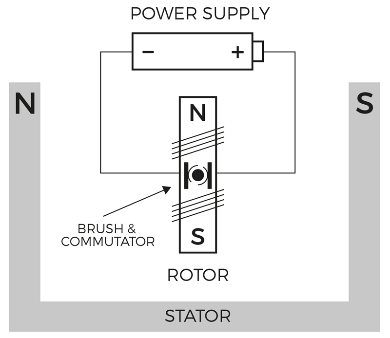
Figure 1. Two-Pole Brushed Motor
Recent years have seen growing adoption of brushless DC motors. They are smoother and more efficient than brushed motors and have lower maintenance demands and higher torque-to-power ratios.
On the other hand, brushless motors are also more expensive and require more complicated drive circuitry. This article explores more of the differences between the two motors and explains why, in many applications, a lower-cost brushed DC motor remains the best option.
Motor Construction and Operation
Brushed DC motors consist of four key components: the stator, the rotor, the commutator, and the brush (see Figure 1).
The stator can be a permanent magnet or electromagnet. It remains stationary and encases the rotor, which consists of one or more windings of wire wrapped around a core made of a ferrous metal, usually iron.
When current passes through the rotor’s coil, it creates a magnetic field which interacts with the field created by the stator, and thus turns the rotor. The commutator is a conductive copper sleeve around the axle of the rotor, which has gaps dividing it into segments. As the axle rotates, it physically disconnects from the brush and reconnects to a different pair of segments. This reverses the polarity of the magnetic field each time the motor completes a half-turn and enables smooth motion.
The brushed DC motor has the advantage that it reverses the direction of current itself, due to the rotation of the commutator, so no external controller is required. On the downside, the brush and commutator can become worn by friction and require maintenance.
There are five types of brushed motor: one with a permanent magnet, and four varieties that use an electromagnet in their stator: shunt-wound, series-wound, compound-wound and separately excited. The most commonly used types are the permanent magnet and separately excited, because of their versatility. Each variant has its pros and cons, which make them suitable for different kinds of applications.
In contrast, a brushless DC motor, as its name suggests, does not uses brushes to commutate the drive current. Instead of changing the direction of current flow through physical contact between brushes and a slotted commutator, the brushless motor uses electronic control circuitry to alternate the direction of current flow. This produces an alternating current from a DC supply and the controller reverses the direction (or phase) of the current each time the motor rotates 180˚ or another fixed amount, such as 120˚ for a 3-phase motor, producing consistent motion.
The brushless motor can provide smoother motion than a brushed motor and usually requires less maintenance. The brushless motor also has a longer lifetime as there is no physical wear on the brush and commutator. It can offer more precise control and higher speeds as well as often delivering a higher power-to-weight ratio. In addition, most brushless motors run the current through a fixed winding with permanent magnets rotating around it; this avoids the complexities of sending current through the moving rotor.
Typical Drive Circuits
The main disadvantage of the brushless motor is cost—both of the motor itself and of the more complex drive circuitry required.
At its simplest, a brushed motor does not require any external controller as the physical change of connection of the brush is enough to keep it rotating. If the application requires the motor to have variable speed or to be able to change direction, some sort of drive circuit is required.
A drive circuit for a brushed motor operates on the principle that the voltage across the motor is proportional to the speed of rotation so altering the voltage allows the speed of the motor to be controlled. Circuits can also reverse the direction the current flows through the motor, thus switching the direction of motion.
In practice, the voltage is often kept constant but rapidly switched off and on again using pulse width modulation (PWM) to achieve an “average” voltage based on the duty cycle. This is more efficient than using a potential divider to reduce the drive voltage.
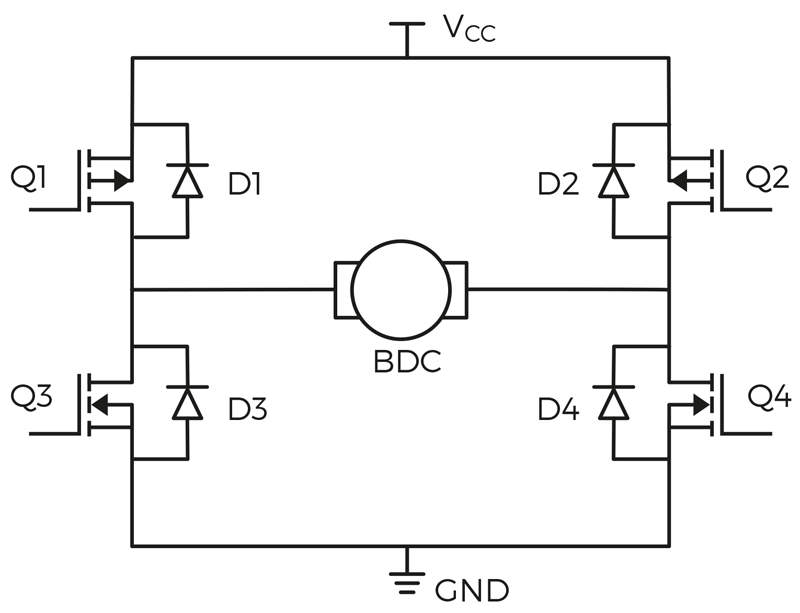
A brushed motor requires only a single transistor and a flyback diode to move in one direction and, as shown in Figure 2, it requires a circuit called an H-bridge if a change of direction is required. The flyback diodes in Figure 2 provide a safe route to ground for the back EMF that could otherwise cause damage. In contrast, a brushless motor requires a full H-bridge to move at all.
The H-bridge uses four transistors to control the current flow: Q1, Q2, Q3, and Q4. When Q1 and Q4 are on, current flows through the motor (labelled BDC) from left to right, causing it to rotate. Alternatively, if Q2 and Q3 are on, the current flows right to left, resulting in rotation in the opposite direction.
Click image to enlarge
Figure 2: H-Bridge Gate Arrangement
For a brushless motor, the complexity in the drive circuit is required to create a varying AC voltage due to the lack of a physical commutator. The control of the varying voltage can be implemented using analog components or digitally using an FPGA or microcontroller. In practice, control is often achieved using all-in-one motor drivers, which integrate the required functions into a single chip.
The control circuitry for a brushless motor may use sensors to detect the position of the motor, so it can switch the driving voltage in time with the rotation. This can be achieved by using an optical encoder or a Hall effect sensor, but the position may also be inferred by measuring the back EMF produced by the motor's windings; this configuration is often referred to as a sensorless BLDC and, while it removes the cost of sensors, it represents additional complexity in the control circuit.
Simple Solutions for Brushed Motors
The following examples show how brushed motors can be controlled in practice.
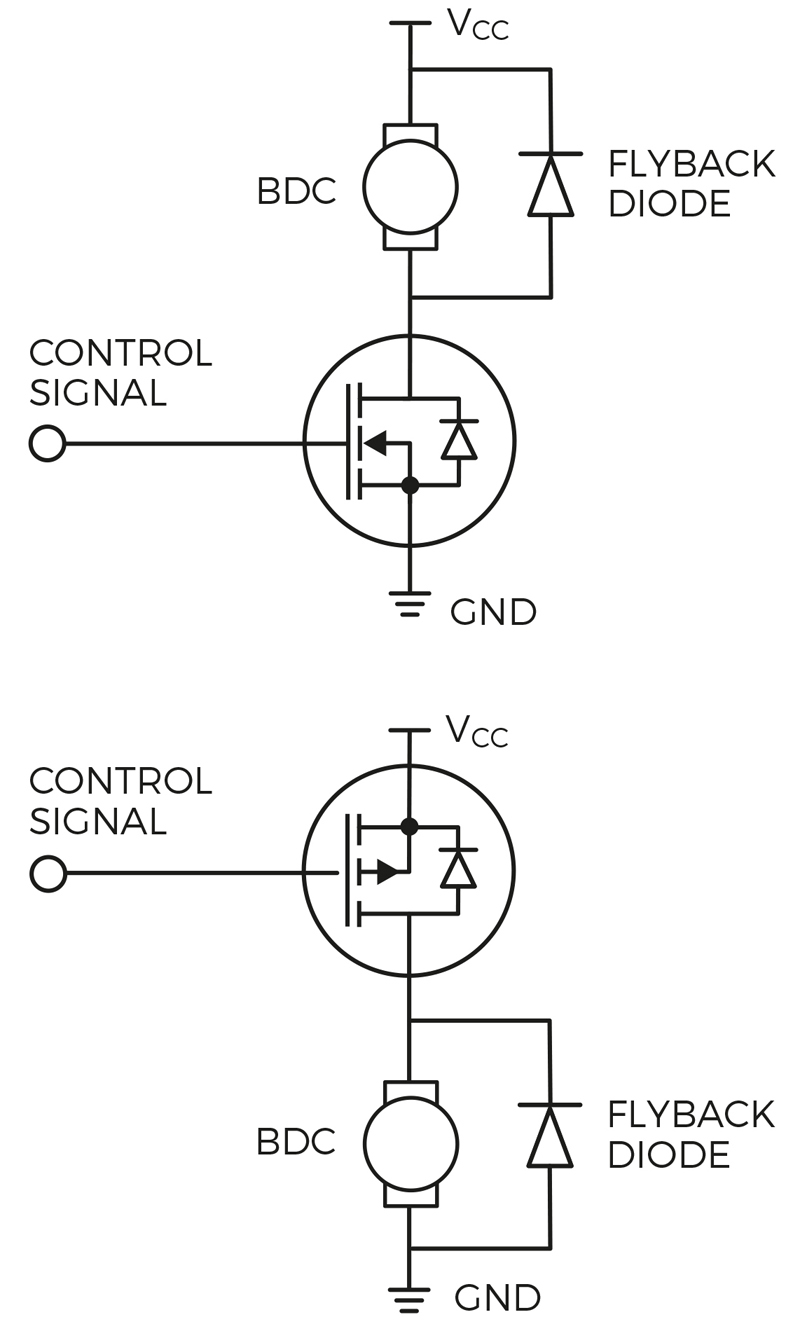
Firstly, for a simple single-direction application, such as a toy, the Diodes DMTH4008LFDFWQ is a MOSFET that provides the required switching to enable speed to be controlled (Figure 3). The device is rugged, operating at up to 175°C; provides high power density, up to 40V and 11.6A; and in a compact 2mm x 2mm package.
Click image to enlarge
Figure 3: Single Direction Brushed DC Motor Control
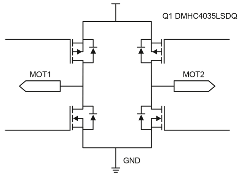
For a bidirectional brushed motor to, for example, move a car’s door mirror, an H-bridge is required (Figure 4). This example uses the Diodes DMHC4035LSDQ, which provides an H-bridge that can switch up to 3A, in a simple, single package. This part can also be used to control a single-phase brushless motor.
Click image to enlarge
Figure 4: Bidirectional Brushed Motor Control
Conclusion
Brushless motors have multiple advantages over brushed motors including: higher efficiency, better control, and a lack of maintenance. In high-end products, such as expensive cars, they may soon completely replace brushed motors.
On the other hand, brushed DC motors are reliable, inexpensive, and require a minimal number of external components to drive them, keeping overall costs down. They will continue to be used in many applications where smooth operation is not important or where use is infrequent, such as in adjustable car mirrors and car seat motors.
Whether your application is best suited to a brushed or brushless motor, the choice of drive circuits is critical to achieving an efficient design that meets your requirements.


