Supplements motor control applications
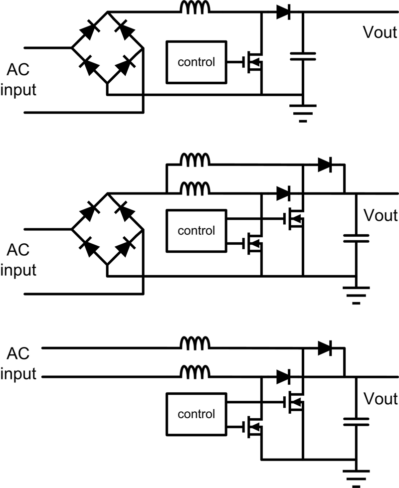
Figure 1: Different PFC circuits
Many AC powered systems above a certain power consumption level require power factor correction (PFC). This is demanded by either utility companies or by governments. PFC sits right at the input of a system behind a diode bridge rectifier but before any input capacitors. The PFC circuitry is intended to make sure that the voltage and current on the input are in phase with each other. In other words, PFC is the ratio of average power delivered to the circuit load to apparent power. This article introduces an easy way to design very flexible and feature rich PFC circuits with Analog Devices ADP1047 and ADP1048 digital PFC controllers with monitoring. This design work is done by using an intuitive graphical user interface. Also the benefits of such an approach in combination with a motor drive application are reviewed. Different PFC circuits PFC circuits typically use a boost DC to DC converter topology right behind the AC rectifier bridge. This topology forces the input current to be in phase with the input voltage. The result is that the load looks like a pure passive load resistor to the AC source. For higher power levels, an interleaved topology can be used. The most common is a two channel interleaved operation. This is nothing different than having two boost converters in parallel and making them share the load. Similar approaches outside of PFC are called multi phase. Step-down (buck) type regulators would use the term �multi phase' if current is distributed amongst different parallel step down circuits and the outputs are combined. In PFC the term �phase' is not used for this function, since it can create a lot of confusion. �Multi phase' is used for PFC circuits for more than one phase of AC supplies coming in. This is why the term �interleaved' is more common to describe the distribution of the load power on multiple parallel boost topologies. For very high power efficiency one can also go bridgeless. In this case the diode bridge rectifier can be omitted. In the interleaved operation with a diode bridge rectifier, the two channels are alternating after each switching period. In the bridgeless topology however, one channel switches during the positive half wave of the AC input voltage and the second channel switches during the negative half wave. Figure 1 shows a principle circuit diagram of these three basic circuits. The top shows the easiest implementation, the middle the interleaved concept and the bottom the bridgeless configuration. Of course many more circuits are possible. For high power and very efficient operation one can combine interleaved operation with a bridgeless setup for example. Obviously such designs require many components and can become quite complex. The ADP1047 is intended for single channel PFC while the ADP1048 offers the capability for interleaved and bridgeless operation. For this purpose it offers a current sharing function as well as two different PWM output signals. Flexibility of using a digital PFC controller Most PFC converters are analog type systems. With today's digital derivates however such as Analog Devices ADP1047 and ADP1048, a designer can take advantage of the great flexibility digital can offer. The loop stability can be optimized for high speed and sufficient stability using a programmed digital filter rather than hardware components. While these devices implement the average current mode control loop, there are actually different loops which can independently be programmed. There is a low and high line current filter as well as fast voltage compensation filters. The output voltage of the PFC can be programmed so that it varies based on the load current. This can increase the power conversion efficiency in the overall system. Also soft-start behavior can be modified in great detail. Monitoring of voltage and current at the input of a system is valuable Besides the digital control loop, the ADP1047 and ADP1048 offer accurate voltage and current monitoring. The input and output voltages are sensed as well as the input current. These sensed analog values are digitized using analog to digital converters. The inductor current which equals the input current is either measured with a current sense resistor directly for highest accuracy or indirectly using two current transformers in series with the power switch or boost diode. In any type of sense method, the sensing can be calibrated in the system to increase the measurement accuracy. Such calibration is typically done together with production testing and the calibration values are stored in the EEPROM of the ADP1047 and ADP1048. Besides voltage and current it is also possible to calibrate an external temperature sensor. The measured information about the voltages and current are used for the operation, control and protection but can also be supplied to other circuitry in the system via PMBus for monitoring purposes. Especially the input power of the PFC is very interesting since it gives information about potential faults in the system. Different interrupt like flags can be set which contribute to a safe and reliable operation of the setup. The voltage and current information as well as register settings can be accessed via the integrated PMBus interface.
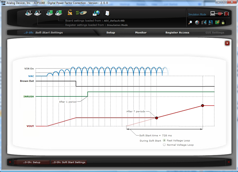
Graphical user interface avoids the need for programming skills Since experienced power design engineers typically are not excellent code programmers, the approach of this PFC solution is to reduce the digital aspect of the circuit to an easy to use graphical user interface (GUI). Figure 2 shows a screenshot of the software. All parameters which can be influenced are graphically shown on the different setup and monitoring screens. This way evaluating and programming the ADP1047 and ADP1048 offers additional safety since the internal state machine of the chips reduces the room for user errors compared to programming a general microcontroller or digital signal processor. One example of the GUI's capability is adjusting the soft-start. By the click of a mouse button, the input voltage threshold for start-up can be adjusted. The inrush current time delay setting is set afterwards. Inrush control is used to pre-charge the output capacitor of the PFC circuit before the circuit starts up. This is often implemented via a relay or MOSFETs. Figure 2 shows in the middle of the screenshot how this inrush timing can easily be adjusted. On the bottom diagram in figure 2 one can adjust the behavior of the soft-start function itself. For this, additional delay time before startup as well as the rise time of the output voltage can be adjusted.
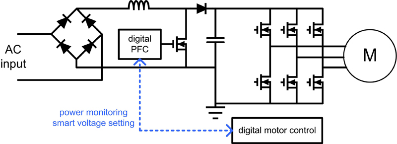
Benefits for motor control applications In motor control applications, there are two ADP1047 / ADP1048 features which are especially beneficial. One is the precision power monitoring to detect faults in the system, the other feature is the capability to adjust the output voltage of the PFC on the fly. Depending on the state of the motor drive, the voltage can be adjusted to increase efficiency without compromising performance. These �smart voltage settings' can be used for cases where the motor is paused or in cases where it is running at very low power. Figure 3 shows the principle diagram of the PFC included into a motor control architecture. PFC easy to use Implementing a digital PFC solution does not necessarily require a steep learning curve if the right controller IC with the right kind of support software is used. Such an implementation is especially valuable for dynamic applications such as in motor control. www.analog.com


