Effective Protection Techniques for Industrial Communications
A detailed look at what types of surge protection are needed for control communications in today’s typical industrial applications
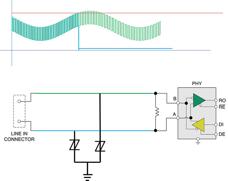
Figure 1: The graph shows AC voltage on a RS-485 line caused by a nearby AC power line
Industrial control communications that use a variety of data bus and control line protocols are susceptible to damaging transients from ESD, load switching, coupled AC energy and induced surges from nearby lightning strikes that can impede the monitoring of sensors and switches as well as the control of industrial motors, heaters, valves and other applications. Ironically, the operation and switching of industrial loads can be a key source of interference with industrial communications.
Moreover, industrial communications are not restricted to factory settings. Elevators, HVAC systems, lighting systems (including exterior signage), rail systems, construction sites and fire/security systems are examples of applications that use industrial communications that warrant special consideration for protection to keep them reliably operating in exposed or harsh environments.
Not considered in this article are common computer data communications protocols such as Ethernet or USB as these have their own specialized protection schemes.
Simple AC Signaling
One of the oldest and most basic control protocols is switching AC-powered remote loads on and off with a simple switch. Over time, this protocol has evolved to signaling remote systems by switching an AC power line off or on. The remote receivers that detect the state of the AC signal line are typically high-impedance inputs that will need simple overvoltage protection schemes found on common AC lines.
Standard Metal Oxide Varistor (MOV) devices are the most common protection devices used, although, for maximum reliability, system engineers may specify higher performance hybrid protectors such as Bourns® GMOV™ or IsoMOV™ devices. These types of hybrid protectors are designed with a GDT in series with the MOV to drastically extend the life of the MOV. This enables additional system reliability while providing an MOV-sized device with considerably enhanced surge ratings and temperature ratings compared to a conventional MOV device solution. Not only does this type of hybrid surge protection save valuable PCB space, it also gives designers extra flexibility to add more features to the application.
Unbalanced Small Signal Communication
A few computer controller signaling protocols have survived and even thrived since they were first deployed decades ago, although they are typically used in applications where distances are not great and the environment is not particularly harsh. Many of these are proprietary systems but one very common protocol is the 28 VAC signaling commonly found in HVAC systems. Often overlooked, failures in HVAC systems can be disastrous and can often be easily protected against with simple and inexpensive solutions.
Small signal protection is best accomplished by TVS diodes or Bourns’ TISP® thyristor devices. These are available as either unidirectional or bidirectional protectors. As silicon-based devices, they offer precise protection threshold voltages in tightly-spaced voltage ranges so that protection can be tailored with precision.
For DC signaling systems, TVS diodes provide optimal protection. They clamp or limit voltages by lowering their impedance once their breakdown voltage is exceeded, and offer a faster response with a lower clamping voltage compared to varistor-based solutions. One advantage of the TVS diode clamping function is that it cannot latch up, making TVS diodes ideal for DC signaling protection.
AC-based protocols such as HVAC controls can use thyristor-based TISP® protection devices that afford higher protection levels than similarly sized TVS diodes. These voltage-operated switches provide protection by shunting incoming surge energy to ground. When the current flowing through them has reached their holding current threshold, TISP® devices then turn off and return to their high impedance state. Because thyristors will reset at every zero crossing of the AC signal, there is no possibility for latch-up problems.
Balanced Line Small Signal Communication
Industrial control system designers have learned that for reliable long-distance control communications, unbalanced, ground-referenced protocols are not sufficient. These ground-referenced protocols are prone to the interference typically found in industrial settings. This includes noisy ground systems that inject interference directly into the communication channel.
The solution is to use two wires for signaling – neither of which is tied or referenced to any ground. The signaling is purely differential in nature. These are known as “balanced two-wire” protocols. In such a system, the vast majority of industrial noise sources will impact both conductors equally. Because the receiver is only looking at the difference between the voltages on the two conductors, the noise that is common to both conductors will be ignored.
The balanced two-wire protocol of choice is RS-485. In this protocol, the signal is a nominal 5 V difference between two conductors that switch polarity to indicate “1” and “0”. As such, a voltmeter connected across the pair will either register +5 V or -5 V but never zero volts. The RS-485 protocol allows the pair to float up to 7 V from ground, allowing for ground loops and other ground differences over tremendous distances.
Such a robust protocol will naturally find its way into the harshest of industrial environments. The long-distance cabling will act as a huge antenna, pulling in interference from noisy motors, power switching, nearby lightning strikes and all manner of electrical noise.
Because RS-485 control lines often run right alongside AC power lines, they may need to be protected from the unlikely but very real possibility of accidental connection to those power lines. This can happen when cables get cut or crushed in industrial accidents. It can also happen during installation or maintenance when wiring errors can be made.
While the RS-485 protocol will maintain a clean data stream during all but the most catastrophic events, it must be protected when the common-mode voltage exceeds the 12 V limit (7 V common mode + 5 V differential mode) of the transceivers used.
Designing a robust protection system for RS-485 has many challenges. Protection designers may specify very large TVS diodes to handle the anticipated surge levels, but such diodes have large capacitances, which can degrade the RS-485 signal. Higher surge expectations happen on longer signal runs which already struggle to maintain signal fidelity.
Another trap is to specify independent overvoltage protection on each signal conductor. One problem that arises in such a design is that one protector may trigger during a marginal surge event and that line will go to ground, but the other remains at the signal level – which can violate the maximum differential limit of the transceiver. This is known as converting a common mode event to differential mode.
Figure 1 illustrates this situation. The graph shows an AC voltage impressed on the RS-485 line by a nearby AC power line. At some point, the “blue” line rises above the trigger level of its thyristor protector, causing it to pull the blue line to near ground. The green line is unaffected, but the difference between the blue and green lines violates the differential input limits of the transceiver, likely causing permanent damage.
One effective solution to this problem is shown in Figure 2. A Bourns® Model TBU-RS TBU® High Speed Protector (HSP) device is employed to protect an RS-485 “PHY” transceiver. It uses small, low-capacitance TVS devices that will not interfere with RS-485 signals operating at even the fastest data rates.

Click image to enlarge
Figure 2: This solution offers core protection of the transceiver by the on-board asymmetric voltage TVS diodes that are customized to provide protection of the peculiar voltage range of the RS-485 protocol. They are effective in enforcing both the differential and common mode voltage limits demanded by the transceiver
These TVS diodes are, in turn, protected from excessive fault currents by the Bourns® TBU® (Transient Blocking Unit) devices, which are Electronic Current Limiters (ECLs). These FET-based devices can be tailored to coordinate perfectly with the TVS diodes and are able to react to fault currents in less than a microsecond, blocking the fault currents from reaching and damaging the TVS diodes. Of course, the RS-485 communications will be interrupted during the surge event, but will recover once the danger has passed. In the event of a continuous power cross event, the TBU® devices will be triggered and reset on every half cycle of the AC power line while still not allowing damage to the TVS diodes or the PHY.
In addition, TBU® HSP devices have a maximum input voltage rating that must be observed. Therefore, a suitable primary protector must be chosen. Here, the designer has flexibility in choosing a primary protector that meets the system protection needs while keeping an eye on the BOM costs.
Primary protection options include high-performance GDTs, such as the Bourns® Model GDT35-11 that can withstand induced surges from nearby lightning surges in excess of 10 kA. High surge rated GDTs are an excellent choice for RS-485 transceivers mounted on rooftops, lighting or power poles and antenna structures.
Bourns’ Power TVS (PTVS) diodes are another very effective primary protection solution for industrial communications. When a PTVS diode experiences a voltage higher than the specified breakdown voltage, it conducts current until the voltage is reduced in amplitude or the surge time has come to an end. Available with surge current ratings of 1 kA to 15 kA, these solid-state protectors take reliability to the next level when application outages simply cannot be tolerated.
Industrial control lines have a unique set of challenges when it comes to reliability. The threats that undermine maximum uptime operation often include the applications themselves. Careful consideration of the control signals being protected can lead to robust designs that will work without nuisance tripping or costly downtime.


