Three-phase power
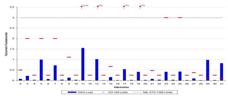
Figure 1: Harmonic Performance
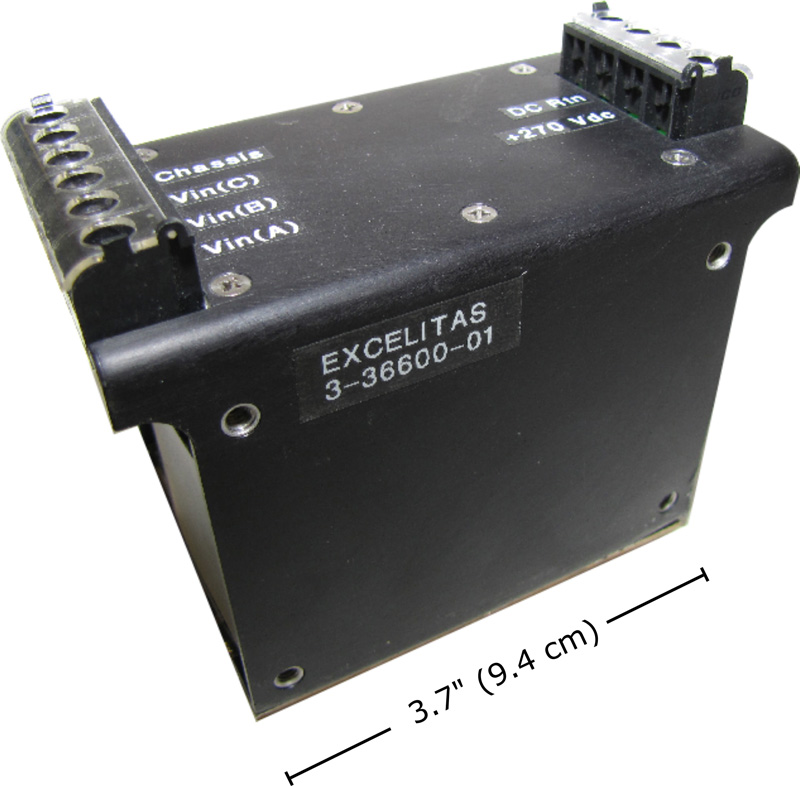
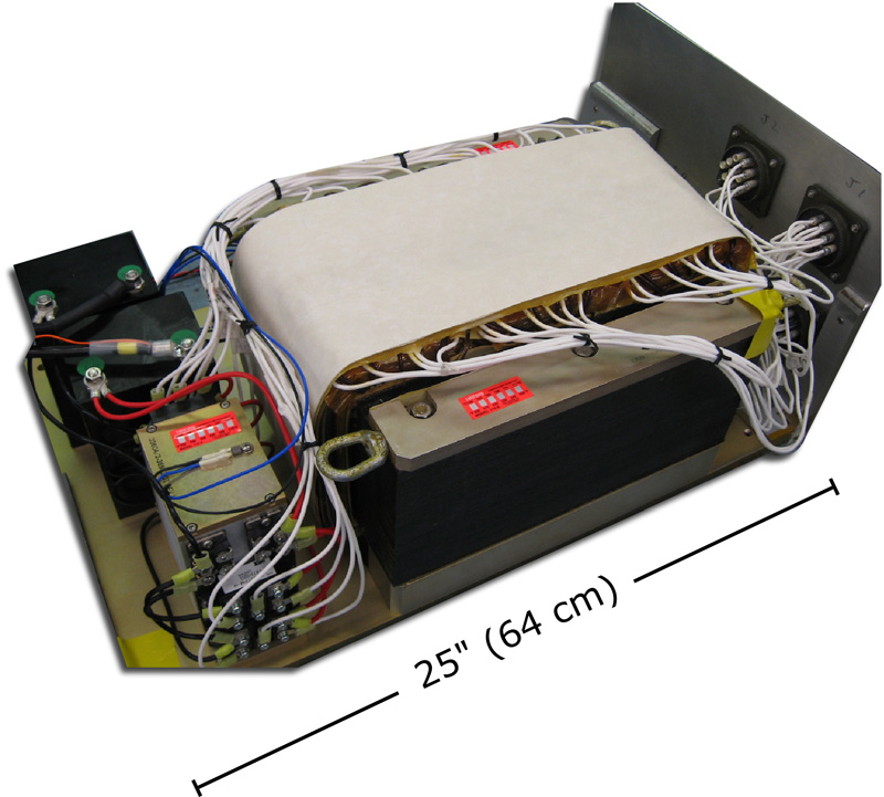
As a designer and manufacturer of critical power systems used in airborne, shipboard and ground-based applications in the defense and commercial markets, Excelitas Technologies recognizes the need to optimize overall system efficiency. The conversion of three-phase power to a DC voltage using a bridge rectifier results in the generation of large line harmonic currents. These result in excess losses in the power distribution network, which is designed to distribute current at the fundamental frequency of the supply, not at high order harmonic frequencies. Harmonic currents also cause harmonic distortion of the voltage waveform of the supply, which adversely affects the performance of rotating machines connected to the same supply, and can cause them to draw more current than they should. For these reasons, it is desirable to convert three-phase to DC voltage in a manner that does not generate significant harmonic currents in the supply. There are also regulatory requirements in some environments. For instance, commercial aircraft power utilization equipment must meet the requirements of RTCA/DO-160, which sets strict limits on the various line harmonic currents as a percentage of the fundamental current. On board Navy ships, MIL-STD-1399 Section 300 specifies a 3% limit for line harmonics. Excelitas offers two solutions to this problem, both of which are applicable to 60 Hz supplies and 400 Hz power systems. The use of a multi-phase transformer-rectifier unit (TRU) has been well known for several decades. In these TRUs, the secondary winding is tapped and "wings" coupled to other phases are connected to produce six, nine or twelve output phases. These phases are rectified by a bridge rectifier with twelve, eighteen or twenty-four rectifiers to produce the DC output current. The line input current becomes a stepped waveform resembling a sine wave; the more steps, the closer it resembles a sine wave, hence the lower the harmonic content. In theory, for a TRU with N phases, all harmonics up to 2N-1 should be eliminated, and the amplitude of the first harmonic should be approximately 1/(2N-1). Excelitas Technologies developed its first TRU twenty-five years ago for a Navy program, which it determined could be met with a fifteen-phase unit, and was subsequently granted a patent for it.1 The fifteen-phase design offers superior performance over designs with fewer phases, but requires close attention to the accuracy of the phase amplitudes and angles, as this directly affects performance. Excelitas has developed techniques to ensure a high degree of control over these parameters. Figure 1 shows the harmonic performance of a TRU in a 400 Hz commercial aircraft system. The amplitudes of the harmonics are shown as blue bars, and the DO-160 limits are shown as red lines. As expected, all harmonics are below the limit up to the 29th; at this frequency, 11.6 kHz, the remaining harmonics are easily removed by a simple EMI filter. Since the introduction of its first TRU, Excelitas Technologies has developed numerous units for 60 Hz and 400 Hz applications, ranging from 750 watts to 25,000 watts. Excelitas also offers autotransformer versions, which are particularly useful in reducing weight in airborne applications. TRUs are often used in high power motor controller applications in aircraft, where electric motors are displacing traditional hydraulic systems for moving the control surfaces of the aircraft. The high thermal mass of the TRU allows these units to be safely overloaded by a factor of three or four for the duration it takes to move the position of the flaps or other control surfaces. Figure 2 and Figure 3 show two examples of modern TRUs. As a rule of thumb, 400 Hz ATRUs weigh approximately 3 pounds per kilowatt, and 60 Hz TRUs weigh about 15 pounds per kilowatt. The variation is due to the extra iron for the magnetic circuit required in a 60 Hz transformer, as compared to a 400 Hz transformer.
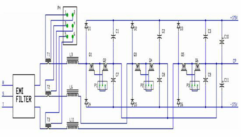
While the TRU is a simple and reliable solution to line current harmonic reduction, some applications require a solution that is smaller and lighter. For these situations, a class of all-electronic converters is available using high-frequency switching, which allows the magnetic components to be shrunk dramatically in size and weight. The schematic of the power train of one such solution is shown in Figure 4. This is akin to three boost converters, such as those used in single-phase power correction circuits. When a bidirectional power switch is turned on, the right-hand end of its inductor is connected to a point that mirrors the neutral point, although the neutral of the power source is not connected, and the magnitude of the current in the inductor increases with its polarity being the same as the instantaneous polarity of the source voltage. When the power switch is turned off, the polarity of the voltage across the inductor reverses and increases in magnitude until one of the rectifier diodes is forward biased and energy is discharged into the output capacitors, C10 and C11, and the load. The input current can be shaped to be sinusoidal by judicious control of the power switch duty ratio. The high-frequency component of the inductor current is removed by and EMI filter (not shown in Figure 4).
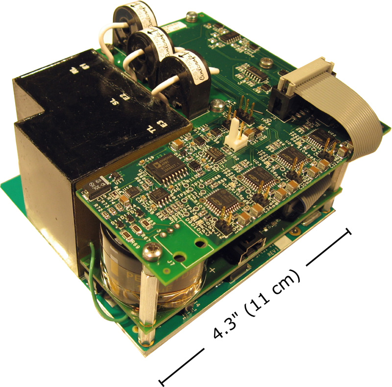
Excelitas Technologies has developed a 5 kW unit using this principal, switching at 400 kHz, and has now moved on to develop a second generation model in which the power switches are connected in a delta configuration, thereby eliminating the artificial center point. The advantages are better utilization of available state-of-the-art semiconductor devices, and improved independent control of the three phase currents, resulting in improved harmonic performance. This configuration is expected to outperform the traditional TRU in terms of harmonic reduction. The 5 kW converter is shown in Figure 5. Because the magnetic components are switched at high frequency, 350 kHz in this case, the same converter can be used in either 400 Hz or 60 Hz applications with only minor changes. The second generation is being developed for wild frequency aircraft applications, where the line frequency can range between 360 Hz and 800 Hz. The converter, not including its EMI filter, occupies 26 cubic inches for a power density of 192 watts per cubic inch. The weight is 1.95 lbs, equivalent to 0.39 pounds per kilowatt. Multiple converters can be connected in parallel with the aid of a simple load sharing circuit, to obtain higher output powers.
The all-electronic solution has already demonstrated performance and efficiency equivalent to the traditional TRU, and is cost-competitive at the 5 kW level. Moving to a digital implementation of the control electronics will greatly reduce the number of parts in the unit, leading to better predicted reliability. In this respect, multiple units in parallel can be used in N+1 redundant configurations, which leads to greatly improved apparent failure rates. Excelitas continues to design and manufacture TRUs and ATRUs for a variety of airborne, shipboard, and ground-based applications. The customer base is comfortable with the simplicity of the solution and its proven reliability. However, Excelitas believes that ultimately the all-electronic solution will displace the traditional TRU as its advantages become apparent and its reliability is proven. www.excelitas.com/ProductPages/Power_Supplies_-_Defense_Products.aspx


