Electrolytic Capacitors for Electric Vehicle Charging
Extending the charging infrastructure for electric vehicles will raise demand for application-optimized components
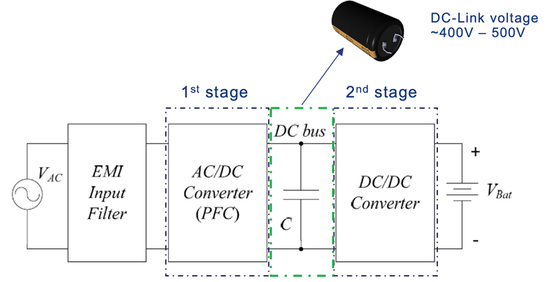
Figure 1. EV on-board charger block diagram showing capacitor-stabilized DC link
Automotive remains one of the fastest growing sectors of the electronics industry as car makers look to new technology to increase safety and reliability, support new connected user experiences, and improve economy and emissions. The evolution to electric powertrains from the traditional internal combustion engine (ICE) is gaining momentum, driven by environmental demands and enabled by ever improving battery and charging technologies. The market for hybrid and full-electric vehicles (EVs/HEVs) is projected to grow at a CAGR of 17%.
Governments are in favor of electric mobility, as one route to meeting pledges on national CO2 emissions. European authorities have already announced a deadline of 2040, by which sales of new petrol and diesel vehicles will be banned. The UK government recently announced plans to consult on bringing that date forwardby at least five years.
From a practical point of view, electric vehicle charging infrastructure needs to be significantly improved within the next few years. More charging stations – often called electric vehicle service equipment, or EVSE - need to be installed, ranging from ordinary domestic wall-box chargers to high-power roadside charging stations capable of fully replenishing long-range batteries in a few minutes.
Although driven by the imperative to protect the planet, the change to electric-only mobility also presents opportunities to develop new-energy technologies that governments and high-tech businesses are keen to capture. Among these, improved battery chemistries, battery management, and techniques for faster charging could make significant advances in the coming years to meet growing demand for longer driving range, shorter charging times, and lower costs.
Faster, More Reliable Charging
The EVSE market is predicted to grow 30% year on year, to meet consumer demands. These can be 250V single-phase AC outlets up to 11kW or higher-voltage 3-phase up to 22kW or 43kW designed to be connected to the vehicle’s On-Board Charger (OBC), or high-speed DC chargers up to 50kW or higher that charge the battery directly. In either case, generating a suitably smooth and stable DC charging supply voltage calls for significant filtering. To meet this demand, KEMET has a portfolio of automotive-grade magnetic components and capacitors of various types including high-voltage C0G ceramic capacitors for use in resonant circuits and DC-link capacitors that can be power-film or large electrolytic devices. Figure 1 shows how electrolytic capacitors are used to stabilize the DC link in an OBC application.
Power Capacitor Innovations
KEMET’s ALA7D electrolytic capacitors, which are available from 180µF to 820µF, and the ALA8D series from 200µF to 620µF with 105°C temperature rating, introduce design innovations to meet the specific needs of OBCs. Although high-temperature operation is not required, because the OBC is active only when the vehicle is not running, the capacitor and electrical connections must withstand the high levels of vibration experienced when the vehicle is being used. Two features help to ensure the desired ruggedness.
In addition, there are important new internal features that enhance vibration resistance. Analysis of ordinary electrolytic capacitors exposed to automotive levels of vibration has shown that excessive movement of the wound element inside the cylindrical metal casing results in the tabs between the wound elements and the terminals cracking due to fatigue stress causing the device to fail. The result is often that the tabs become completely disconnected.
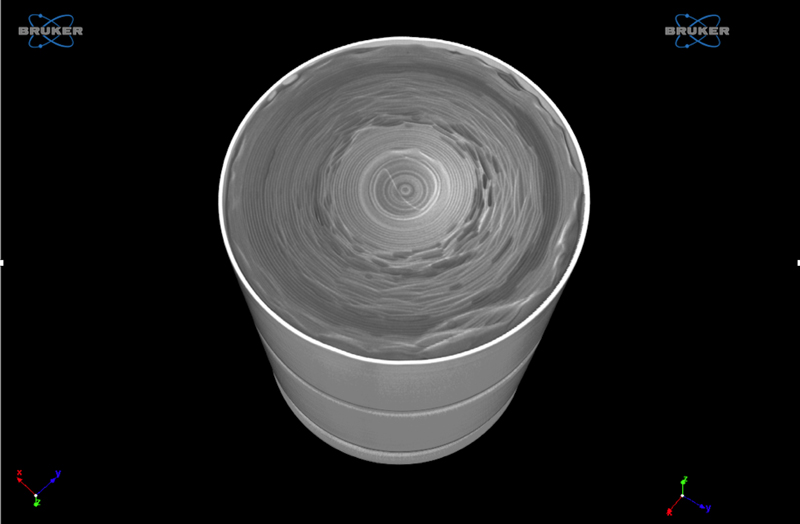
To enhance vibration resistance in the ALA series capacitors, KEMET developed a new manufacturing process that allows tight control of the outer dimension of the wound element. The diameter is calculated to ensure an extremely snug fit inside the capacitor casing, which additionally features a special straight-sided design. Moreover, the winding is made with an extended cathode that becomes crushed against the end of the casing when inserted thereby preventing vertical movement when the capacitor’s deck is put in place. Figure 2 is a computed-tomography (CT) scan that shows the close fitting of the wound element inside the casing and the cathode-extension crush designed to hold the winding securely in position.
Click image to enlarge
Figure 2. Internal view of vibration-resistant capacitor
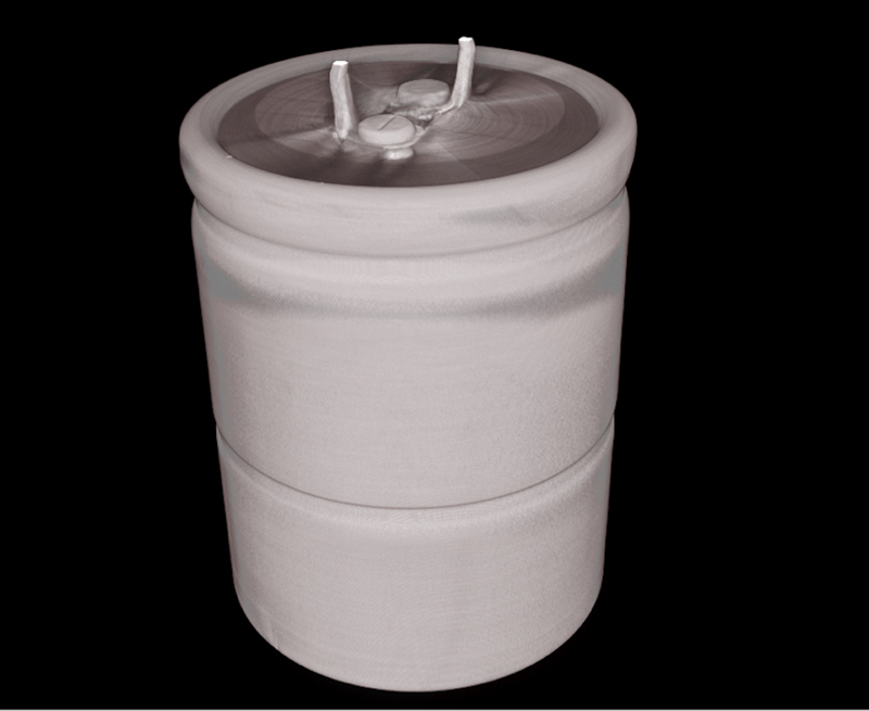
After the winding is tightly inserted, the casing is then grooved not just once, as normal to create a seating for the end-seal, but also a second time to create a further anti-vibration groove that prevents radial movement of the winding. Figure 3 shows a CT scan of the fully assembled capacitor, clearly displaying the conventional end-cap groove and additional anti-vibration groove.
Click image to enlarge
Figure 3. CT scan showing shock groove to prevent radial movement
The result is a doubling of the vibration capability, compared to the standard electrolytic capacitor construction. This enables the ALA series capacitors to pass vibration testing in accordance with MIL-STD-202G referenced in AEC-Q200, the automotive standard for stress resistance. The devices pass the toughest level defined in the military standard, Test Condition D, which specifies exposure to 20g for four hours at 10-2000Hz.
The new construction also helps meet tight constraints on space and weight. The larger diameter wound element ensures increased capacitance without increasing the case volume thereby allowing smaller capacitor banks that trim size, weight, and bill of materials costs. Understanding that an OBC may typically contain between six and nine electrolytic capacitors, or as many as 12, to ensure a stable DC charging voltage for the battery, designers can achieve valuable cumulative savings by choosing devices that are properly optimized for the application.
Another advancement utilizes Press-Fit technology, which not only allows easy and fast assembly but also ensures more reliable connections than conventional snap-in terminals for large capacitors. They are capable of lasting the lifetime of the vehicle. The option of Press-Fit installation, which enables solder-free interconnects, lets assemblers avoid the challenges associated with placing large electrolytic capacitors on the OBC circuit board, and soldering terminals onto heavy copper traces. It allows the capacitors to be inserted after the board is cleaned following the solder process to prevent cleaning liquid entering and damaging the components.
Maximizing Capacitor Reliability
When using electrolytic capacitors in a mission-critical application, such as an automotive OBC, it is important to ensure the devices can satisfy the specified minimum lifetime requirement. To help engineers make their own assessments, KEMET has published a capacitor life calculator that can be freely accessed at https://elc.kemet.com/. Additional tools are available to help optimize device lifetime when working individually with customers.
The ALA7D series of vibration-resistant capacitors are rated from 400-600V, operate from -40°C to 85°C, and have a calculated lifetime of 15,000 hours at 85°C. The 400V-500V ALA8D series is specified from -40°C to 105°C and has a rated 8,000 hours lifetime at 105°C. The devices also have high ripple current and surge-voltage ratings that help ensure high electrical reliability.
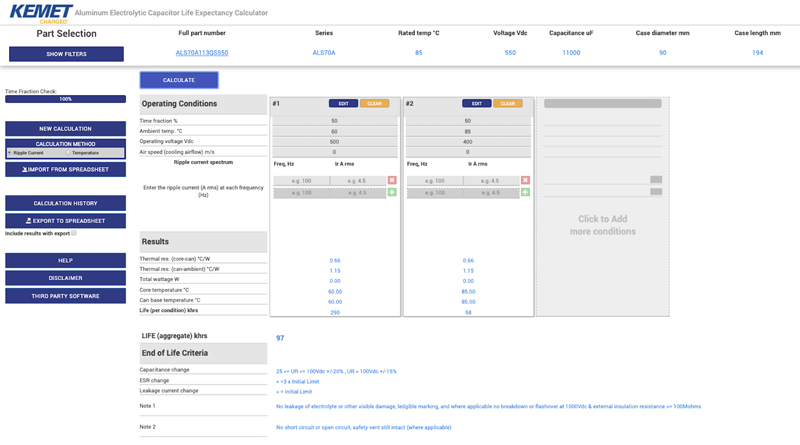
Box-Out Section: About the KEMET Electrolytic Capacitor Life Calculator:
The life calculator at https://elc.kemet.com/ (see diagram) lets engineers assess the theoretical life expectancy of their chosen electrolytic capacitors under the application operating conditions. Based on application details such as the duty cycle, ambient temperature and provisions for cooling, operating voltage, and ripple currents, as well as end-of-life criteria such as capacitance loss, change in ESR, or change in leakage current, the lifetime can be automatically calculated.
Click image to enlarge
Figure 4. Assessing capacitor reliability using the KEMET life calculator
Conclusion
Electric vehicles can take a central role in the drive to make personal mobility cleaner. Continued evolution of electronic components is needed, to tailor characteristics for OBC equipment. The latest generation of snap-in electrolytic capacitors introduce innovative construction that not only ensures vibration resistance beyond the base requirement of AEC-Q200, but also increases volumetric efficiency resulting in valuable size, weight, and cost savings.