Sensorless Field Oriented Control (FOC) for energy efficient motors
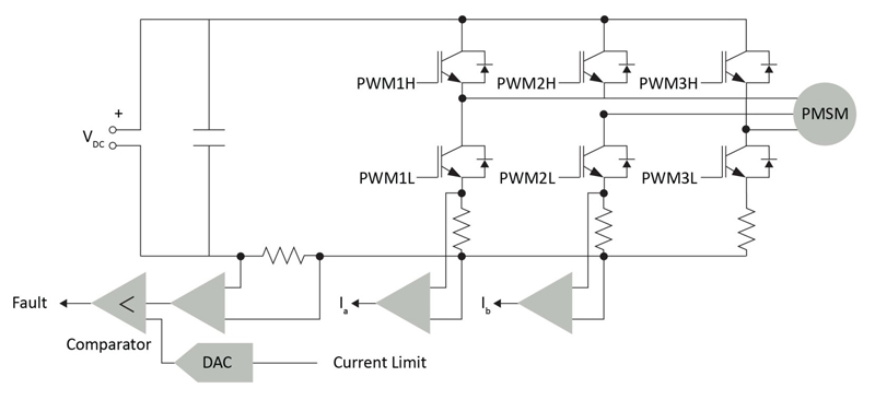
Figure 1: A three-phase sensor-less PMSM control system that uses a three-phase voltage source inverter
There are two main driving factors behind the adoption of advanced motor control systems based on Permanent Magnet Synchronous Motors (PMSMs) with sensor-less Field Oriented Control (FOC): improving energy efficiency and strengthening product differentiation. While a PMSM with sensor-less FOC has been proven to achieve both objectives, success requires a design ecosystem that provides a holistic implementation approach. A holistic ecosystem will enable designers to overcome the implementation challenges that have hindered its adoption.
Why PMSM?
A PMSM motor is a brushless motor that uses electronic commutation. It is often confused with the Brushless DC motor (BLDC) - another member of the brushless motor family that also uses electronic commutation but has slight differences in construction. PMSM construction is optimized for FOC, while the BLDC motor is optimized to use a 6-step commutation technique. The optimization results in the PMSM having a sinusoidal Back-Electromotive Force (Back-EMF), and the BLDC motor to have a trapezoidal Back-EMF.
The rotor position sensors used with each of these motors are also different. The PMSM typicaly use a position encoder while BLDC motors use three Hall sensors for operation. If cost is a concern, designers can consider implementing sensor-less techniques that eliminate the cost of the magnet, sensors, connectors and wiring. Eliminating sensors also improves reliability as there are fewer components that can potentially fail in a system. When comparing a sensorless PMSM to a sensorless BLDC, the sensorless PMSM using an FOC algorithm delivers better performance while using a similar hardware design with a comparable implementation cost.
The applications that will be the biggest beneficiaries of a switch to PMSM are those that are currently using a Brushed DC (BDC) or an AC Induction Motor (ACIM). The key benefits of switching include lower power consumption, higher speed, smoother torque, lower audible noise, longer lifespan and smaller dimensions, making the application more competitive. However, to realize these benefits from using a PMSM, a developer needs to implement the more complex FOC control technique along with other application-specific algorithms to meet system requirements. While a PMSM is more expensive as compared to a BDC or an ACIM, it offers substantially more advantages.
Implementation Challenges
Realizing the advantages of using a PMSM, however, requires an understanding of the hardware complexities inherent with implementing an advanced FOC motor control technique, and the domain expertise that is required. Figure 1 shows a three-phase sensor-less PMSM control system that uses a three-phase voltage source inverter. Controlling the inverter requires three pairs of high-resolution PWM signals which are interlinked and plenty of analog feedback signals which require signal conditioning. The system also requires hardware protection features for fault tolerance, designed using high-speed analog comparators for fast response. These additional analog components required for sensing, control, and protection increase the solution cost which are not required for a typical BDC motor design or for simple Volts per Hertz (V/F) control of an ACIM.
There is also the development time required for defining and validating the component specifications for the PMSM motor control application. To address these challenges, designers can select a microcontroller that offers a high level of analog integration with the device specifications tailored for PMSM motor control. This will reduce the number of external components required and optimize the bill of materials (BOM). Highly integrated motor control devices are now available with high-resolution PWMs to facilitate implementing advanced control algorithms, high-speed analog peripherals for precision measurement and signal conditioning, hardware peripherals necessary for functional safety, and serial interfaces for communication and debug.
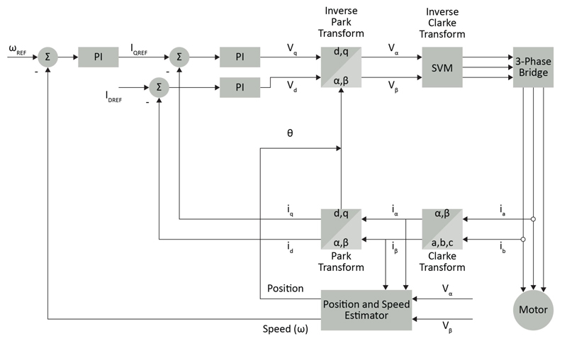
Equally challenging is the interaction between the motor control software and the electro-mechanical behavior of the motor. Figure 2 shows the standard sensor-less FOC block diagram. To take this from a concept to an actual design requires an understanding of the controller architecture and digital signal processor (DSP) instructions for implementing math-intensive time-critical control loops.
Click image to enlarge
Figure 2: Block diagram of a standard sensor-less FOC
To achieve reliable performance, the control loop must execute within one PWM period. There are three reasons that necessitate control loops to be time optimized.
1) Constraint: Use a PWM switching frequency at or beyond 20KHz (50uS time period) to suppress the acoustic noise from the inverter switching.
2) To achieve higher bandwidth control system, the control loop must execute within one PWM period.
3) To support other background tasks such as system monitoring, application-specific functions and communication, the control loop needs to run even faster. As a result, the FOC algorithm should aim to execute in less than 10uS.
Many manufactures provide example FoC software with sensor-less estimators for the rotor position. However, before it can even start rotating the motor, the FOC algorithm must configure various parameters to match the motor and the hardware. Further optimization of the control parameters and coefficients is necessary to meet the required speed and efficiency targets. This is achieved through a combination of: 1) deriving the parameters using the motor datasheet and 2) experimentation by a trial-and-error method. Developers will have to resort to the trial-and-error method when the motor parameters may not always be accurately characterized in the motor datasheet, or when the designers do not have access to high-precision measuring equipment. This process of manual tunning takes time and experience.
PMSM motors are used in many different applications, operating in different environments or with different design constraints. For example, in a car radiator fan, it is possible that the fan blades may be rotating freely in the reverse direction due to wind when the motor is about to be started. Starting the PMSM motor with a sensor-less algorithm under this condition is a challenge and it can potentially damage the inverter. One solution is to detect the direction of the rotation and rotor position and use this information to slow the motor to a standstill through active braking before starting the motor. Similarly, it may be necessary to implement additional algorithms like Maximum Torque Per Ampere (MTPA), torque compensation and field weakening[1] etc. These types of application-specific add-on algorithms are necessary to develop a practical solution, but they also add to design complexity by increasing development time and complicating software verification.
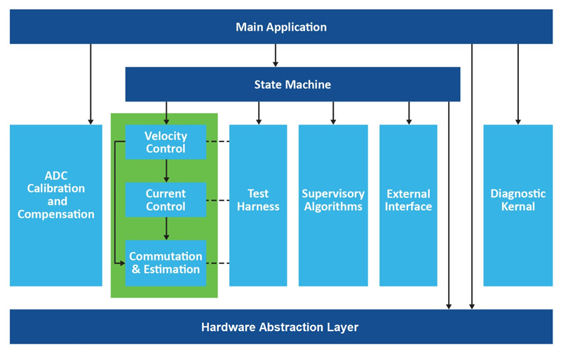
One solution to reduce complexity is for designers to create a modular software architecture that enables the application-specific algorithms to be added to the FOC algorithm without affecting the time-critical execution. Figure 3 shows the software architecture of a typical real-time motor control application. At the heart of the framework is the FOC function, which has a hard timing constraint and many application-specific add-on functions. A state machine within the framework interfaces these control functions with the main application. The architecture needs a well-defined interface between software function blocks to make it modular and facilitate easy code maintenance. A modular framework supports the integration of different application-specific algorithms along with other system monitoring, protection and functional safety routines.
Click image to enlarge
Figure 3: Application framework for FOC
Another benefit of a modular architecture is the separation of the peripheral interface layer (or hardware abstraction layer) from the motor control software, which enables designers to migrate their IP seamlessly from one motor controller to another as the application features and performance requirements change.
Requirement for a Complete Ecosystem
Addressing these challenges demands a motor control ecosystem that is tailored for sensor-less FOC designs. The motor controller, hardware, software and development environment should all work together to simplify the process of implementing advanced motor control algorithms. To accomplish this the ecosystem should have the following features:
1. A high-level tool to automate motor parameter measurement, design control loops and generate source code, enables designers without domain expertise to implement FOC motor control and write and debug complex time critical code which are very time consuming
2. An application framework for FOC and different application specific add-on algorithms reduces the development and test time
3. Motor controllers with deterministic response and integrated analog peripherals for signal conditioning and system protection in a single chip reduces the total solution cost
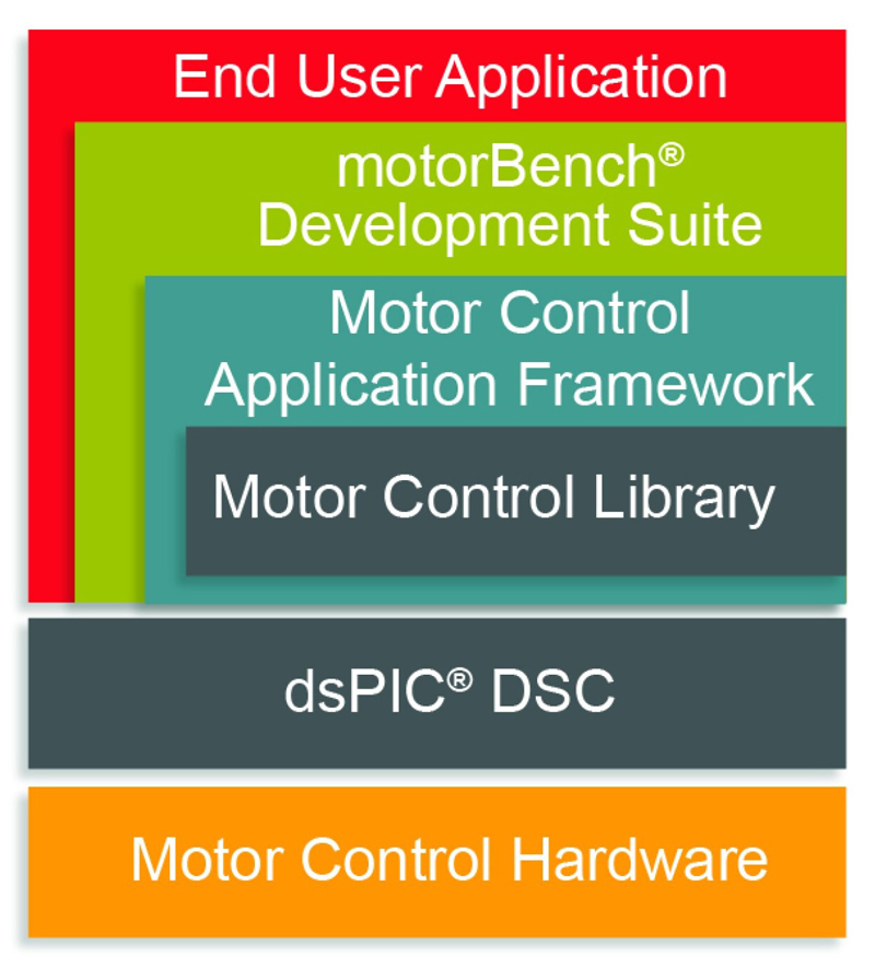
Figure 4 shows an example of a motor control ecosystem architecture that includes the application framework and a development suite for a high-performance dsPIC33 motor control Digital Signal Controller (DSC). The development suite is built around a GUI-based FOC software development tool that can measure critical motor parameters and automatically tune the feedback control gains. It also generates the required source code for a project created in the development environment utilizing a Motor Control Application Framework (MCAF). At the heart of the solution stack is the Motor Control Library, which makes it possible to implement the application’s time-critical control loop functions and interact with the dsPIC33 DSC’s motor control peripherals. This GUI works in conjunction with several available motor control development boards to support motor parameter extraction, and FOC code generation for a wide range of LV and HV motors.
Click image to enlarge
Figure 4: Microchip Technology motor control ecosystem architecture
The transition to brushless motors has been motivated by the need for high energy efficiency and product differentiation. A comprehensive motor control ecosystem provides a holistic approach to simplifying the implementation of sensor-less FOCS with PMSMs, and should be comprised of dedicated motor controllers, rapid prototyping development boards and easy-to-use FOC development software for automating code generation.


