Flash corruption: software bug or supply-voltage fault?
Answer: Both!
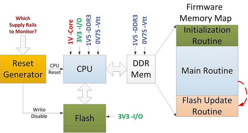
Figure 1: Typical CPU section and firmware memory map
Embedded systems commonly use Flash memory to store firmware. Occasionally, the firmware stored in the Flash memory in some systems is accidentally corrupted, preventing the system from booting up after powering on. Flash corruption is commonly associated with a software bug. However, it is also commonly understood that the probability of Flash corruption increases either during power-cycling tests or during margining tests. The Flash corruption problem tends to be more severe when the number of complex ASICs or SOCs a board uses increases. Fortunately, methods exist to minimize occurrences of Flash corruption that are not due to software faults. Flash memory corruption Figure 1 illustrates a typical circuit board's CPU circuitry. When the power turns on, the reset generator first activates the CPU reset signal. It then waits until the power to the CPU, the Flash memory, and the DDR memory each reaches its correct level, waits for an additional extended period of time—about 150 ms—and then deactivates the CPU reset signal. When the reset signal deactivates, the CPU begins to execute the initialization routine in the Flash memory, transfers the contents of the firmware stored in the Flash memory into the DDR memory and then executes the program from the DDR memory. The procedure to load firmware into the Flash memory is: (1) Firmware is downloaded into the DDR memory through a communication interface. (2) Jump to the Flash-update routine to reprogram the Flash with the new firmware. (3) Power to the processor is recycled and the new firmware takes effect. An event that causes the code execution to jump inadvertently to the Flash-update routine can corrupt the Flash memory contents. When the board power is cycled, the corrupt version of the code is loaded into the DDR and the board does not function as expected. The code execution could jump to this Flash-update routine inadvertently due either to a software bug or to a faulty supply voltage rail (during the power-off event, for example). Normal debugging methods can detect a software bug. However, a faulty power supply voltage is hard to detect, as the supply voltage error can occur anywhere. Supply-fault-induced execution jumps All ICs have both minimum and maximum operating voltage specifications. If the system exceeds an IC's maximum voltage specification, damage to the device results. If the supply drops below the minimum supply level, the device no longer operates as specified. For example, the core-voltage specification of the CPU in figure 1 is 1.2 V �5%. If the voltage drops below this level, the ability of the CPU's internal instruction execution pipeline to reliably transfer instructions and data is compromised and—depending on the CPU's process and operating temperature—the instruction can incorrectly execute. As an example, a move instruction could execute as a pop instruction, and the code execution then jumps to a random memory location determined by the contents of the stack. Depending on the contents of that memory location and the error in execution, the processor can either hang or jump to the Flash-update routine, corrupting the Flash memory and overwriting the Flash memory contents. A droop in DDR memory voltage or threshold voltage also introduces errors in the instructions and data transferred between the memory and CPU. This erroneous code execution can also cause a jump to the Flash-update routine, corrupting Flash memory. Supply-voltage droop The power-supply voltage droop can occur for either of the two following reasons. Card power down: When the power to the board turns off, not all supplies on the board turn off at the same time because the turn off rate depends on a number of parameters including the supply capacity, load, and supply-output capacitance. Because the power-supply turn-off slew rate is slow in comparison to the processor's instruction execution speed, the processor can experience a supply fault, causing it to mis-execute instructions before the supply is fully off or before its reset signal activates. Momentary ground-voltage rise: The power consumption of some processors can fluctuate dynamically, depending on the executing instructions. When such changes occur, the device draws large amounts of current for brief periods from the power source, and dumps these into the ground. As a result, the supply voltage can momentarily droop and the ground voltage may increase. The duration of such a condition depends on the inductance of the supply path. Minimizing corruption The probability of Flash corruption can be minimized by activating the CPU reset when any supply rail drops below its threshold level. This prevents code execution under faulty power supply conditions. The reset generator activates both the CPU-reset signal as well as the write-protection signal to the Flash memory. In some cases, the reset generator output does not apply directly to the CPU. Instead, it connects to a CPLD, which executes a reset-distribution algorithm. In such cases, the write-protection signal for the Flash should be set because the CPU may not reset as soon as the power-supply voltage becomes faulty. The reset generator IC in figure 1 monitors all CPU rails—1 .0, 3.3, 1.5, and 0.75 V—and activates the reset signal and Flash write-protect signals when any one of them drops below their operating threshold levels. Selecting a reset generator The criteria for selecting a reset IC include the number of voltage-monitor inputs, glitch filtering, hysteresis, fault-detection accuracy (across the operating-temperature and -voltage ranges), and fault-detection speed. Number of voltage-monitor inputs: The reset-generator IC must monitor all CPU voltage rails for faults—voltage excursions below corresponding operating threshold levels. In the case of figure 1, four inputs are required with thresholds set at 5% below the nominal operating voltage levels. For example, Lattice power management ICs support six to 12 voltage-rail-monitor inputs, and the reset generation threshold levels can be programmed from ?0.5% to ?20%. Errors to avoid: Some designs use a single-rail reset generator that usually monitors only, for example, 3.3 V. This will not be sufficient, because the 3.3V rail may turn off at a different rate than the core voltage or the DDR voltage. This arrangement could work only if all critical loads used the 3.3 V as their input supply. In most circuit boards, however, the power supply for the core and DDR use different input-voltage sources due to power dissipation, and so reset generation using only 3.3V cannot avoid Flash corruption. The same argument holds if the reset generator monitors only the core supply rail. Glitch filtering: When the reset generator has single-ended, as opposed to differential, sensing of voltage rails, differences in the ground voltage between the reset IC and the CPU memory can generate false reset signals. To make sure that the reset is actually due to a fault in the supply voltage and not a momentary ground voltage difference, reset ICs include glitch filters. For example, when their input glitch filters are enabled, Lattice power-management ICs ensure that the fault persists for 64 microseconds before activating the reset signal. Reset generators using ADCs and microcontrollers to monitor voltages implement ADC sample-averaging algorithms to eliminate the effects of glitches, resulting in false reset activation. The averaging algorithm derives the actual ADC voltage by calculating the average of four ADC voltage samples. Hysteresis: Most voltage rails source from switched-mode power supplies. The output of these supplies usually contain ripple. This ripple can cause a reset signal glitch when the supply level is close to the reset threshold. To avoid this, reset generators must have hysteresis voltage levels ranging from 0.5% to 1% of the voltage monitored. Reset generators using ADC and microcontrollers to monitor voltages should implement hysteresis in software to prevent glitches in the reset output.
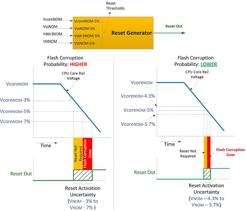
Fault-detection accuracy: For the purpose of this discussion, assume that the lowest operating voltage of the CPU is VNOM ? 5%, where VNOM is the nominal core voltage, and that when the supply turns off, VNOM reduces linearly at a rate of 2%/ms. The accuracy of a reset generator is a measure of uncertainty in its ability to detect a given voltage threshold. For example, a reset generator monitoring a VNOM ?5% threshold with an error of 2% can activate the reset output anywhere between VNOM ? 3% to VNOM ? 7%. The processor continues to execute instructions until the reset signal activates. Consider two reset generators with assumed zero propagation delay (figure 2): one with an accuracy of 2% (left) and the other with an accuracy of 0.7% (right). As can be seen, the supervisor with 2% error has a much wider uncertainty range than that of the reset generator with 0.7% accuracy. While the reset-output activation within the orange zone prevents the processor from executing even though the supply is healthy—an irritant—the activation in the red zone is its inability to prevent the processor from corrupting the Flash memory. Clearly, the narrower the reset generator's threshold uncertainty, the lower the probability of Flash corruption. The accuracy of Lattice power management devices is 0.7%. Some designs use the power-good signal from DC-DC converters to determine the health of supplies and use a CPLD to generate reset signals. This method does not reduce the probability of Flash corruption because the accuracy of the power good signals from DC-DC converters ranges from 4% to 20%. Also, some designs use low-cost comparators to monitor the voltages. In this case, one has to pay attention to voltage reference, resistor accuracy, and comparator offset errors. For example, for a voltage-monitoring circuit to maintain 1% accuracy across voltage and temperature, one has to use a comparator with < 1-mV offset error, a VREF with an accuracy < 0.5%, and 0.1% resistors to set the fault-detection threshold.
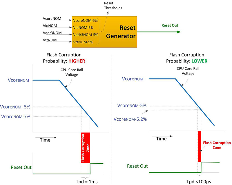
Fault detection speed (Tpd): For the purpose of this discussion, assume that the voltage-monitoring error of the reset generator is 0%. Fault detection speed is a measure of the time required for the reset generator to activate the reset-output signal from the time the voltage crosses the fault threshold or the reset generator's fault propagation-time delay (figure 3). In the left side of the figure, the reset generator requires 1 ms to activate the reset signal. The voltage continues to droop and, by the time the reset signal is active, the supply voltage at the CPU is 7% below its nominal operating voltage. This allows about 1 ms for the CPU to corrupt the Flash. When the fault detection speed is less than 100 ?s, the voltage at the CPU is VNOM ? 0.2%, and the probability of Flash corruption is exponentially less. Lattice power-management devices are able to activate the reset signal in about 64 ?s with the glitch filter turned on, or 16 ?s with the glitch filter turned off. Some designs use a microcontroller with an ADC as a reset generator. In such arrangements, the voltage-monitoring routine activates the reset signal, based on a 10 to 50 ms real-time-clock interrupt. Consequently, the reset can activate with a delay of 10 to 50 ms. Because of this long delay, this method will not be able to prevent Flash corruption. Note that an ADC's errors and the error associated with the on-chip ADC voltage reference determine the voltage monitoring accuracy of an ADC. The number of ADC bits is not a measure of its accuracy. Summary The conventional thinking—that Flash corruption is due only to a software bug—results in engineers wasting time looking for one that does not exist. Flash corruption can occur after the power input to the board disconnects. The only way to minimize the chances of Flash corruption is by holding the processor in reset when there is a supply-voltage fault. The probability of Flash corruption can be significantly reduced by using a more accurate (< 1% voltage-fault-detection error) and faster (fault detection speed < 100 ?s) reset generator. Lattice Semiconductor


