Foundations of Quiescent Current in Linear Power Systems
Design engineers are increasingly looking to minimize power consumption in order to extend battery life.
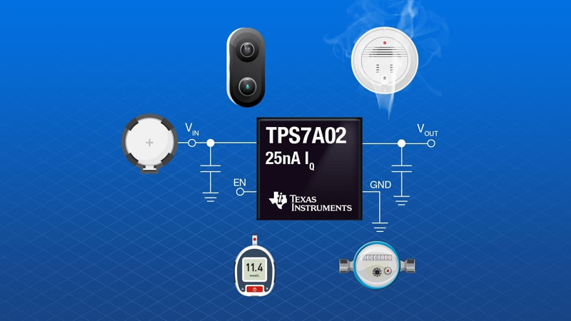
Figure 1. Common battery-powered applications that use LDOs
With many portable medical devices, consumer electronics and building automation products now relying exclusively on battery power, design engineers are increasingly looking to reduce power consumption to get the most they can from their batteries.
Figure 1 depicts some of the most common applications for which power consumption is a challenge, including portable blood glucose monitors, wireless smoke detectors and smart water meters. To minimize power consumption, these products must spend a majority of time in standby mode. One way to reduce overall system power consumption is to select a device that minimizes its ground or quiescent current (IQ). In this paper, I will go over one of the most common power-management devices for minimizing current – linear regulators or low-dropout regulators (LDOs) – and explain how IQ affects the use of LDOs in battery-powered systems.
What is an LDO?
An LDO is responsible for managing power by converting a higher-voltage supply down to a stable lower voltage. When compared to other power-management devices such as traditional DC/DC converters, LDOs are easy to use and are often placed after a DC/DC converter as a post-regulator or connected direct-to-battery to ensure a noise-free voltage supply.
At a fundamental level, the P-channel metal-oxide semiconductor (PMOS) LDO architecture shown in Figure 2consists of a pass device such as a PMOS field-effect transistor (FET), a voltage reference to provide an accurate voltage, an error amplifier to control the negative feedback loop to match the voltage reference, feedback resistors to determine the output voltage, and an output capacitor for stability.
Click image to enlarge
Figure 2. A PMOS LDO
What is IQ in a LDO?
LDO data sheets list three parameters that resemble one another:
· IQ refers to the current drawn by the LDO in an enabled and no-load condition. For LDOs, the main contributors of IQ are the voltage reference and error amplifier.
· Ground current (IGND) is often interchangeable with IQ and refers to the same current consumed by the LDO; when the LDO is in a low-load state, this consumption is typically in the microampere range.
· Shutdown current (ISHDN) is the current drawn when a LDO is in a non-enabled condition, with the battery still connected to the system.
Most data sheets refer to these parameters because most systems have three states of operation:
· Active mode is when the expected load of an application is actively performing a function or operation.
· Low-power mode will be a low load, typically in the range of microamperes to nanoamperes, instead of an ideal no-load condition.
· Off is off; the only power consumption in this state is the leakage current of the battery and system itself.
Knowing the differences between the three parameters and three states of operation enables designers to optimize their power architectures depending on the application.
How IQ affects LDOs – the basics
When optimizing your system for IQ, your first consideration is the actual value of IQ for an LDO. You must select devices that minimize the amount of total IQ consumed by the system in order to extend battery life. Fortunately, with LDOs, calculating how much IQ contributes to a system’s power loss can be fairly straightforward. Equation 1 dictates the relationship between IQ and the overall power consumption of the system, PD:
(VIN - VOUT) × IOUT + (VIN × IGND) = PD
Let’s say that you used the Texas Instruments TPS7A05 LDO to regulate power to a 1.8-V wireless microcontroller from a 3-V CR2032 coin-cell battery with a capacity of 235 mAh. If the microcontroller requires an output current of 100 µA in active mode, and the TPS7A05 has 1.3 µA of IGND at that load, plugging those values into Equation 1 results in:
(3 - 1.8) × 0.0001 + (3 × 0.0000013) = 123.9 µW
When the application switches to low-power mode, IQ plays a much greater role in power dissipation. Continuing the previous example, if the system goes into low-power mode and IOUT becomes significantly lower – 2 µA – using the same LDO (IGND will go down to 1 µA at that load) results in a PD of:
(3 - 1.8) × 0.0000002 + (3 × 0.000001) = 5.4 µW
In this example, IQ represents 56% of the total power dissipated. This becomes an important design parameter for applications that spend a majority of their time in low-power modes, such as smart meters, heat and smoke detectors, thermostats, and smartwatches.
But what about situations when the product is off? As I mentioned earlier, the only power consumption to consider is from the battery leakage and devices within the system. Since the LDO and other power-management devices would be non-enabled, engineers need to use ISHDN when determining power consumption in this state in place of IQ. A product’s power consumption in this state is dominated by a combination of ISHDN, battery leakage (dependent on battery type and chemistry) and output capacitor leakage (which varies based on manufacturer and external conditions).
In order to minimize this power consumption, designers have implemented a simple solution in the form of a battery isolation tab, which prevents the system from consuming any power. This tab results in excellent shelf-life of low-drain products such as clocks or thermostats. Products that require the use of a high-drain rechargeable battery such as smartphones and wearables will never come out of the box 100% fully charged due to this power-consumption phenomena. That’s why manufacturers recommend fully charging such devices before first-time use.
How IQ affects a LDO – dropout conditions
Another way that IQ affects LDOs is how IQ behaves when introduced to a dropout condition. Dropout, or more specifically the dropout voltage, refers to the minimum differential that the input voltage must maintain above the output voltage for proper regulation. Dropout determines how efficiently an LDO operates while still maintaining output voltage regulation. A decrease in the input/output voltage to near-dropout brings the drive voltage of the FET gate in the LDO and various other circuits to their operating limits. In dropout, when all of these internal circuits are saturated, there is often a large rise in IQ similar to that shown in Figure 3. Modern LDOs use a more balanced, differential drive circuitry to maintain reasonable IQ, even in dropout.
Click image to enlarge
Figure 3. Typical LDO IQ behavior in dropout conditions
LDOs have a reputation as inefficient power devices because their efficiency can be determined by the output power divided by the input power (Equation 2):
Efficiency = ![]() × 100%
× 100%
It is also possible to define IQ as the difference between the input and output current (Equation 3):
IIN = IOUT + IQ
Using Equation 3, you can see the importance of minimizing both the dropout and IQ in order to increase efficiency. If the input voltage and output voltage are predetermined in the system, efficiency will result in Equation 4, current efficiency:
Current efficiency = ![]() × 100%
× 100%
In order to achieve the highest current efficiency, having the lowest IQ possible is absolutely critical for optimizing power consumption.
Returning to the previous example, the TPS7A05 will have an overall power efficiency of 59% in active mode and a much lower efficiency of 40% in low-power mode, as shown in Table 1 (IGND in place of IQ because there is a load current). Selecting a device with minimal IGND will maximize current efficiency in both modes, which will help increase overall efficiency and allow you to meet a stricter power budget. If the previous example had used theTPS7A02 instead, which has an inherent IQ of 25 nA, and IGND of 250 nA then low-power mode efficiency would increase by 19% to 59%, driven by the increase in current efficiency due to the predetermined input and output voltages. This further confirms that while IGND isn’t as meaningful of a parameter when in active mode, it is absolutely critical to consider it in low-power-mode situations. You will also see an improvement in shelf life given the ISHDN of 3 nA compared to the 100 nA ofthe TPS7A05.
Click image to enlarge
Table 1. Power efficiency comparison
How IQ affects an LDO – transient response
Your final consideration when designing with low IQ devices is dynamic performance, which refers to the device’s load or line transient performance. Traditionally, low-IQ LDOs have had fairly slow response times, leading to larger disturbances from load and line voltage transients. As a general rule, low-IQ LDOs will have slower transient response times than high-IQ LDOs because it takes current to charge and discharge the internal nodes when a transient occurs. The less current flowing through the internal nodes, the more time it takes to charge the parasitic capacitances internal to the LDO.
When comparing LDOs with small differences in IQ, you cannot assume that different LDO designs will have better or worse transient response, since they will also have different internal structures that may lead to faster or slower response times. An LDO with an IQ of 1 mA will most certainly have a faster transient response than an LDO with an IQ of 1 µA. Having the output voltage respond quickly to changes in load or line voltage with minimal deviation is critical when powering sensitive analog and digital loads such as smart meters, portable medical devices, Internet of Things nodes or smartwatches. These applications spend a majority of their time in low-power mode, which means that the system must shift quickly into active mode and back into low-power mode.
The load transient response is the change in output voltage when there is a change in the load current. Depending on the LDO, the load transient response may differ. Figure 4 shows the load transient response of the TPS7A02 when the device experiences a change in load current from 1 mA to 200 mA in 1 µs. The output voltage drops approximately 145 mV, but then settles back to the nominal output voltage in less than 5 µs. In Figure 4, notice the overshoot during the other side of the load transient; this type of behavior is common for LDOs, since unlike a switching regulator, LDOs do not have a low-side FET capable of pulling the output lower when it rises too high. The LDO’s response time determines the magnitude of the overshoot, but how long the output voltage takes to come back to regulation is determined by the load, which has to discharge the output capacitor.
Click image to enlarge
Figure 4. TPS7A02 load transient response
The line transient response is the change in output voltage when there is a change in the input voltage. Figure 5 shows the line transient response of the TPS7A02 when the device experiences a change in input voltage from 2.8 V to 4.8 V at a 1-V/µs slew rate. Line transients will differ depending on the application, but what is important is the slew rate driving the input voltage. Generally, the slower the slew rate, the less the output voltage deviation. This response is fairly important in applications that can experience any type of input voltage change, such as motor drives in drones.
Click image to enlarge
Figure 5. TPS7A02 line transient response
Conclusion
Understanding how IQ and dynamic performance affect an LDO will help you select power-management devices for battery-powered systems. The first step when selecting a power-management device is to determine whether it can perform the regulation based on the input and output voltage, the load current and the target IQ. Once you know these parameters, you can get a basic idea of the load profile based on the use cases of the system and begin comparing, starting with data-sheet graphs. If you need additional bench measurements, actual devices and evaluation modules will ultimately validate whether or not the device is suitable for your application. There are many misconceptions about LDOs, and knowing these differences will help you optimize your device selection and ultimately simplify the LDO design process.


