Generation 7, 1200V ultrafast trench IGBTs for high efficiency
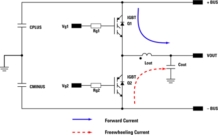
In order to achieve higher efficiency in a grid tie inverter, the correct choice of power semiconductor devices becomes very important. For grid tie inverters, the bus voltage is in the order of a few hundred volts. IGBTs are the most suitable power device choice from the point of view of cost and efficiency. Grid tie inverters typically operate at 20kHz switching frequency and therefore, require ultrafast IGBTs with balanced switching and conduction losses. A typical schematic for DC to AC sinusoidal inverters used for grid tie application is shown in Figure 1. The inverter bus voltage is typically derived directly from a series connected PV arrays or through an intermediate boost converter that is not shown here.
For a 230Vac output inverter for instance, the DC bus voltage is typically +/- 400Vdc. Figure 1 shows IGBT current flow in the forward direction when IGBT Q1 is turned on and the inverter is delivering positive current. When IGBT Q1 is turned off, the current in the inductor has to continue and flows in the copack diode of IGBT Q2. The voltage stress across Q1 is the sum of the DC bus which is 800V. Including voltage spike due to parasitic inductance and rate of current change (di/dt), 1200V IGBTs are typically selected for Q1 and Q2. The same analysis can be done when the inverter is delivering negative current when IGBT Q2 is turned on. In this case, the freewheeling current path is through the copack diode of IGBT Q1. International Rectifier recently released a series of Generation 7, 1200V ultrafast trench IGBTs intended for high frequency applications. These IGBTs are the extension of IR's previously launched 600V trench IGBTs that have become industry de-facto in high frequency inverter applications. By utilizing thin wafer technology, these 1200V IGBTs are able to achieve typical voltage drop (Vceon) of 1.7V and typical fall time of less than 100nsec at their nominal current ratings. They also exhibit a positive Vceon temperature coefficient which allows for easy paralleling. Another benefit of thin wafer technology is the reduction in junction to case thermal resistance (Rth(j-c)) and improvement in the transient thermal response of the IGBT. Four die sizes representing current ratings of 20A, 30A, 40A and 50A are available in popular lead-free packages: TO247/Super TO247 discrete and copack versions and are shown in Figure 2. The IGBT dies are also available in wafer forms for engineers designing power modules. The package versions are switched at four times the nominal current with 960VDC bus voltage at final test. This ensures all weak IGBTs are screened before they leave the factory. The parts without diodes are introduced to give design engineers flexibility to choose their own diodes either for cost or performance reasons. An example of an application that does not require a copack diode is power factor correction or boost converter. Here, the function of the diode across the IGBT is only as protection in case there is current flowing from Emitter to Collector of the IGBT. A small external diode will be sufficient as oppose to a high performance copack diode which saves the cost of the overall system.
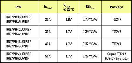
Figure 3 shows a typical turn off event of the 1200V/20A, IRG7PH35UDPBF, ultrafast trench IGBT at junction temperature of 150oC.
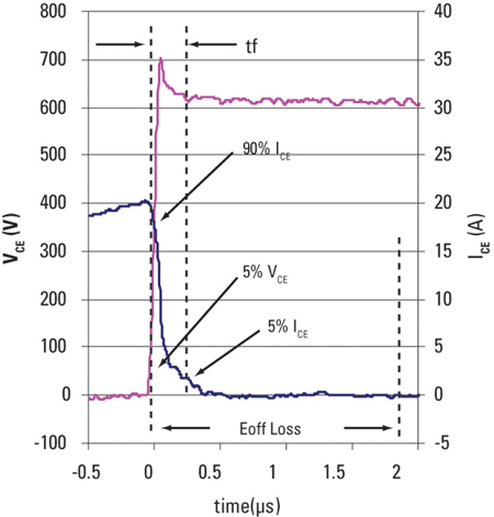
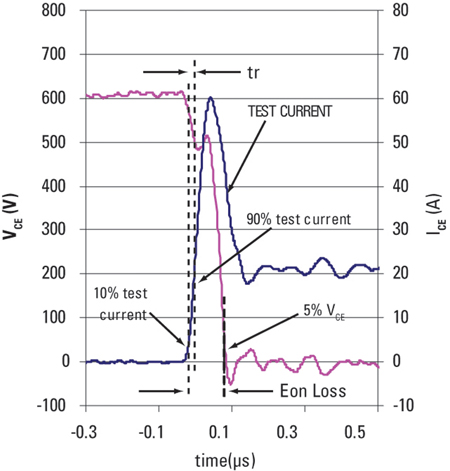
It can be seen from Figure 3 that the cross over between voltage and current during turn off transition contributes to switching loss and needs to be minimized by making the fall time and tail current as small as possible. This generation IGBT is able to achieve a balance loss between conduction and switching at 20kHz by utilizing both IR's trench gate and thin wafer technologies. Another important feature is the low rate of current change (di/dt) which results in lower voltage spike at turn off. It can be seen that with a bus voltage of 600Vdc, the voltage overshoot across the IGBT is only slightly more than 700V which is much lower than the breakdown capability of the device. Also, there is lack of voltage ringing at turn off which might contribute to overall system EMI reduction. The diodes in the copack IGBT versions are 1200V fast recovery low Qrr diodes which provide lower total power dissipation compare to high Qrr diodes typically found in motor drive IGBTs. Having a fast recovery diode is important in minimizing turn on transition loss of the IGBT. As the IGBT Q1 turns back on, the current on the output inductor of Figure 1 will flow again in the forward direction. This current is the combination of load current and reverse recovery current of diode copack IGBT Q2. The shorter the turn on transition, the lower IGBT turn on loss will be. The turn on transition of the IGBT at 600Vdc, 20A and at junction temperature of 150oC is presented in Figure 4.
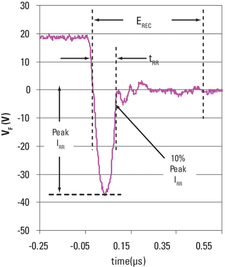
Although the trade-off of low Qrr diode is in its higher voltage drop (Vf), the benefit of having low Qrr still outweighs it. On a grid tie inverter the copack diode will have to take the same IGBT peak current during the freewheeling period when the IGBT is turned off. However, the duty cycle is opposite to that of the IGBT. Therefore the conduction loss of the diode is a much smaller portion of its reverse recovery loss and is typically within a 1 to 3 ratio. Figure 5 shows a typical IRG7PH35UDPBF copack diode recovery waveform at 600V, 20A at Tjunction = 150oC. Here, it can be seen, the recovery of the diode is very fast and the recovery current decays to zero and transfers to the IGBT in about 100nsec.
By selecting the right power device for a grid tie inverter, design engineers can achieve the highest efficiency possible. Recently released Generation 7, 1200V ultrafast trench IGBTs offer balanced conduction and switching losses at 20kHz by reduction in Vceon, fall time and tail current. Copackage with low Qrr diodes, the package part version will reduce power dissipation further. This generation is also available as stand alone discrete device without copack diode for cost or performance improvement. In addition, the die version is available in wafer forms for engineers designing for power module applications. www.irf.com


