
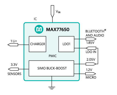
Hearable devices are an emerging market at the intersection of wireless stereo earbuds and fitness monitoring. However, the small form factor escalates the miniaturization challenge for electronics and presents additional challenges for battery life. This article presents an innovative power management system that delivers power with high efficiency in a very small space, while enabling longer battery life for miniaturized hearable devices (Figure 1).
Typical Power Management Implementation
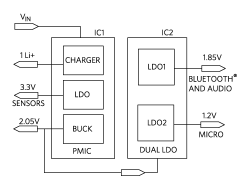
A typical hearable power management system is shown in Figure 2. A power management IC (PMIC) uses a battery charger, a buck converter, and an LDO to power the sensors. A second IC, a dual LDO, powers the microcontroller, Bluetooth, and audio. For simplicity, the external passives are not shown.
Click image to enlarge
Figure 2. Typical Hearable Power Flow Diagram
The Typical Power Tree
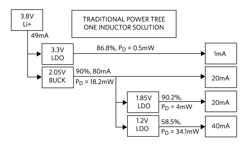
The complete power tree for a typical implementation is shown in Figure 3. The heavy use of LDOs results in an overall efficiency of only 69.5%.
Click image to enlarge
Figure 3. Typical Hearable Power Flow Diagram
Typical Solution Size
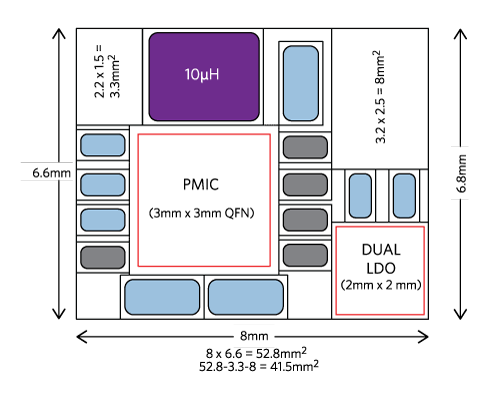
All of the active and passive components of the power flow diagram in Figure 2 are included in the solution shown in Figure 4.
This typical hearable solution occupies a PCB area of about 41.5mm2. The relatively low level of integration as well as the use of multiple LDOs and bigger passives results in a solution that is inefficient in terms of both space and power.
Click image to enlarge
Figure 4. Typical Hearable Solution (41.5mm2)
An Innovative Solution
The power management IC in Figure 5 (MAX77650) integrates the battery charger and regulation needed to power the sensor (3.3V), the microcontroller (1.2V), the Bluetooth, and audio (1.85V), all in one chip. The small PMIC eliminates the wasted space associated with using multiple packages. A single-inductor-multiple-output (SIMO) buck-boost regulator implements three switching regulators that utilize a single inductor, which reduces the necessary space. In addition, high-frequency operation allows the use of a small inductor, further minimizing the required space. One LDO is on-board for noise-sensitive loads. For simplicity, the external passives are not shown.
Click image to enlarge
Figure 5. MAX77650 Highly Integrated PMIC
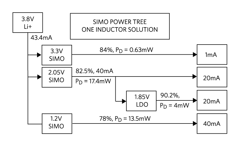
The MAX77650 Power Tree
Figure 6 shows the PMIC power tree with each regulator’s output voltage, load current, efficiency and power dissipation (PD). Three of the four loads connect to the Li+ battery via a high-efficiency SIMO switching regulator. The fourth load is powered by the LDO from the 2.05V SIMO output, which achieves 90.2% efficiency (1.85V/2.05V). The overall system efficiency is an outstanding 78.4%.
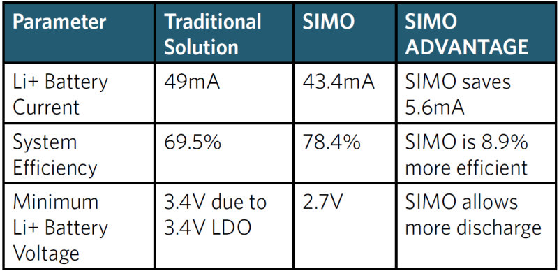
A comparison between the power performance for both solutions is shown in Table 1.
Click image to enlarge
Figure 6. MAX77650 Power Tree
Click image to enlarge
Table 1. SIMO Advantage vs. Traditional Solution
The superior efficiency of the SIMO solution results in significantly lower battery drain, while its wider operating range, down to 2.7V, prolongs the untethered operation of hearable devices.
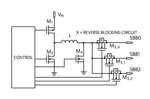
The SIMO Converter
Figure 7 shows the block diagram of the SIMO converter (all components, except the inductor, are integrated). The beauty of this architecture resides in its ability to incorporate three switching regulators that utilize a single inductor. The switching regulators deliver power with minimum losses and the clever architecture eliminates the need to have one inductor for each switching regulator.
Click image to enlarge
Figure 7. SIMO Power Block Diagram
Inductor Current Sharing
In hysteretic, discontinuous current-control mode, the inductor builds up current with M1 and M4 ”on” at the rate of VIN/L. When it reaches a set limit, the current is delivered to the selected output via the M2 and M3_x transistors, as shown in Figure 8. Outputs are serviced in the order requested by their output comparators.

Click image to enlarge
Figure 8. SIMO Current Waveforms
Buck-Boost Architecture Advantage
One of the main features that differentiates a hearable device from a standard stereo Bluetooth headset is the integration of one or more optical or inertial MEMS sensors. The optical sensors use the reflection from an integrated LED to measure blood oxygen saturation, pulse rate, or other vital signs. To generate sufficient light intensity, the LEDs need to run at a higher range of voltage (4V to 5V) than the typical range of Li+ batteries. Designers have a difficult choice: add a buck-boost to the system, which requires yet another IC; add another inductor and more capacitors, which takes up valuable space and volume; or sacrifice the signal-to-noise ratio and risk inaccurate measurements and a poor user experience. The SIMO buck-boost architecture solves this problem by using any one of the outputs set to the desired voltage (up to 5.5V) to drive the LED and optimize sensor performance.
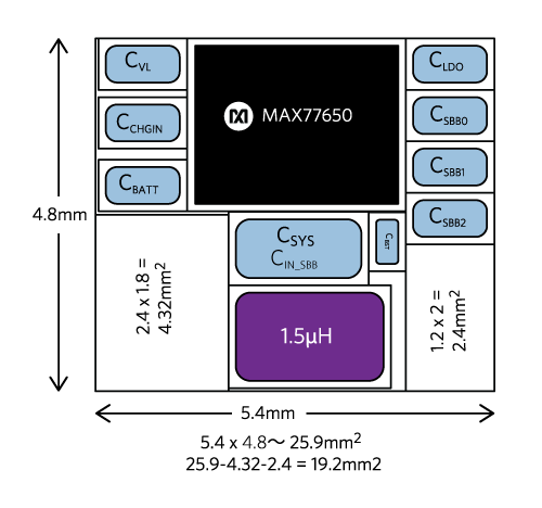
More Battery Life in a Smaller Space
Thanks to its SIMO switching regulators and its efficiently biased LDO, the small MAX77650 PMIC (a 2.75mm x 2.15mm x 0.8mm WLP) delivers power with minimum losses in a PCB space that isless than half of a typical implementation. The solution layout in Figure 9 accounts for all active and passive components.
Click image to enlarge
Figure 9. MAX77650 Solution (19.2mm2)
The total occupied board space is a mere 19.2mm2. In addition, the MAX77650 draws only 300nA in standby mode and 5.6µA in active mode. This saves valuable battery life and again helps reduce the system size by allowing the use of the smallest battery possible while prolonging the use time between each charge.
More Options
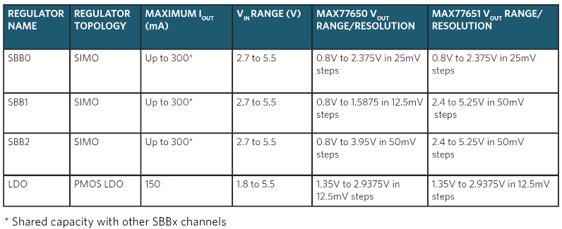
A similar device, the MAX77651, supports applications that require a higher output voltage range. Table 2 summarizes the output voltage ranges and currents for the MAX77650 and MAX77651.
Click image to enlarge
Table 2. MAX77650 and MAX77651 Output Voltages and Currents
More Features
The highly configurable linear charger supports a wide range of Li+ battery capacities and includes battery temperature monitoring for additional safety (JEITA).
The devices include other features such as current sinks for driving LED indicators and an analog multiplexer that switches several internal voltage and current signals to an external node for monitoring with an external ADC. A bidirectional I2C interface allows for configuring and checking the status of the devices.
An internal on/off controller provides a controlled startup sequence for the regulators and provides supervisory functionality when the devices are on. Many systems have one power management controller and one processor and rely on the on/off controller to be the master controller. In this case, the on/off controller receives the wakeup events and enables some or all of the regulators in order to power up a processor. That processor then manages the system.
Numerous factory programmable options allow the device to be tailored for many applications, enabling faster time to market.
Conclusion
We reviewed a typical hearable solution with a low level of integration that leads to inefficiencies in terms of both PCB space and power consumption. Thanks to a unique SIMO architecture, the MAX77650 and MAX77651 PMICs efficiently deliver more power in a smaller space, enabling longer battery life and smaller form factors for hearable devices.
Glossary
BUCK. Step-Down Switching Regulator.
LDO. Low-Dropout Linear Regulator.
JEITA. Japan Electronics and Information Technology Industries Association
LED: Light Emitting Diode.
Li+: Lithium-Ion.
MEMS. Microelectromechanical Systems.
PMIC. Power Management Integrated Circuit.
SIMO. Single-Inductor Multiple-Output.
About the Authors
Scott Kim is an executive business manager for Maxim’s mobile power business unit. He has 20 years of semiconductor industry experience, holding positions in business management, marketing, and applications engineering. Scott graduated from KAIST with an MBA.
Chad L. Olson is a senior-principal product definer in Maxim Integrated’s Mobile Power group who focuses on optimizing the customer product experience through better power management.
Nazzareno (Reno) Rossetti, PhD EE at Maxim Integrated, is a seasoned Analog and Power Management professional, a published author and holds several patents in this field. He holds a doctorate in Electrical Engineering from Politecnico di Torino, Italy.


