Author:
Zhen Yu & Shamim Choudhury, Texas Instruments
Date
04/30/2015
 PDF
PDF
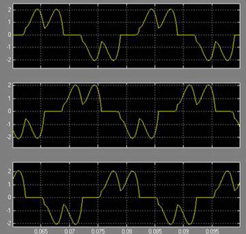
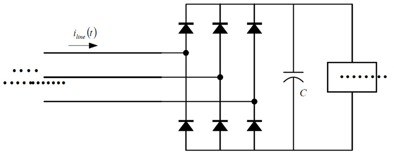
The use of power diodes and Thyristors in applications such as small and large appliances, such as UPS systems, AC/DC rectifiers, and variable speed motor drives is the primary source of harmonic distortion in AC grid or mains current. Due to the source impedance of the mains power, the harmonic load current causes harmonic distortion in the mains voltage. Non-linear industrial loads such as power converters, arc furnaces and motor drives can cause high disturbances including harmonics, sags, spikes, and unbalances in currents and voltages. Figure 1a & b show an illustration of harmonic distortion caused by a three-phase diode bridge.
Click image to enlarge
Figure 1a. Diode rectifier caused harmonic current distortion
Click image to enlarge
Figure 1b. Diode rectifier caused harmonic current distortion
Current and voltage harmonics in mains power, together with other power quality problems, can negatively impact the proper operation of electrical loads because of:
• Over temperature in the load
• Tripping of circuit breakers and fuses
• Damaged capacitors
• Reduced load performance such as torque ripple, vibration and noise
• Damage of motor winding and iron
• Increased leakage through the EMI filter that makes it difficult to meet EMI requirements
• Increased power losses
To minimize these negative effects, different types of power conditioning solutions, ranging from passive filters to active power converters, are adopted by the industry. An Active Power Filter (APF) is an active power converter solution that’s employed to attenuate or eliminate the harmonic distortions in current or voltage and other power quality problems such as voltage sag, spikes and unbalance.
Passive filtering
Passive filters that are composed of capacitors and inductors are commonly employed as power conditioning solutions as well. They are commonly found in such equipment as back up UPS systems, power strips and appliances. The aim of passive filters is to attenuate the harmonics since they cannot totally eliminate the harmonics and often face the problem of series or parallel resonance. Passive filters are not the focus of this discussion.
Let’s explore the types of APFs and topologies and make an attempt to link the topological requirements to microcontroller (MCU) features and capabilities needed to control an APF. In addition, a block diagram level overview is given for the control scheme of shunt APF to indicate the types of mathematical capabilities required in such applications. Finally, a quick overview of Texas Instruments’ (TI’s) C2000 MCUs will provide an example of capabilities and features that are critical for an APF.
APF types, topologies, and controller requirements
The main function of an APF is the cancellation or compensation of current and voltage harmonics. However, additional functions such as reactive power compensation (VAR compensation), current and voltage unbalance correction, neutral current elimination, voltage spike elimination, and voltage regulation are also often accomplished by the same APF solution. There are many APF types and topologies. There are also different ways to connect an APF to the power lines. The following are just a few examples.
Voltage Source Inverter (VSI) Type of APF
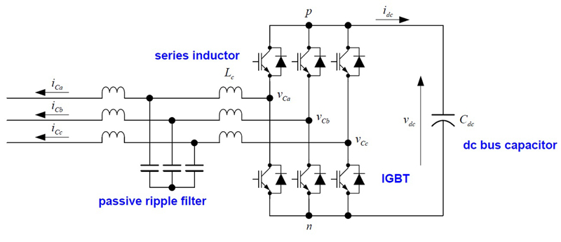
The core of this topology is a three-phase grid-tie (or current mode controlled) inverter with a bulk capacitor acting as energy storage and maintaining the DC bus voltage. A standard six-switch three-phase inverter bridge or multi-level three-phase inverter bridge for high voltage levels can be employed. Figure 2 is an illustration of such a VSI.
Click image to enlarge
Figure 2. VSI type of APF
Shunt APF vs Series APF
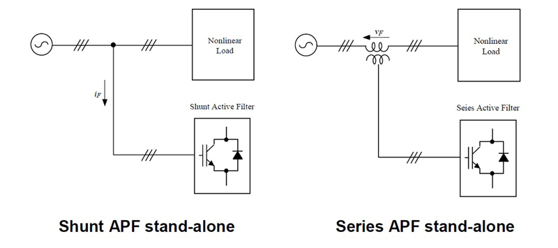
A shunt APF directly injects current into the power wires. Shunt APFs can be used to eliminate current harmonics, compensate for reactive power (to achieve Power Factor Correction), and balance unbalanced phase currents.
A series APF injects a voltage delta into the mains supply voltage by transformer coupling. Series APFs can be employed to eliminate voltage harmonics, regulate and balance terminal voltages, and attenuate harmonic propagation.
Figure 3 is an illustration of shunt and series APF types.
Click image to enlarge
Figure 3. Shunt and series APFOther APF Topologies
There are many other APF topologies. The following are some examples.
A combination of shunt and series topologies sharing the same energy storage DC link capacitor is sometimes called Uniform Conditioner or Unified APF. This approach achieves the benefits and functions of both topology types.
A combination of active and passive filtering is sometimes called hybrid APF. Depending on the specific combination, some additional benefits can be achieved. The combination of a series APF and a shunt passive filter, for example, reduces the size and cost of passive components in the passive filter and magnetics in the APF and is therefore quite popular.
Shunt APF Control
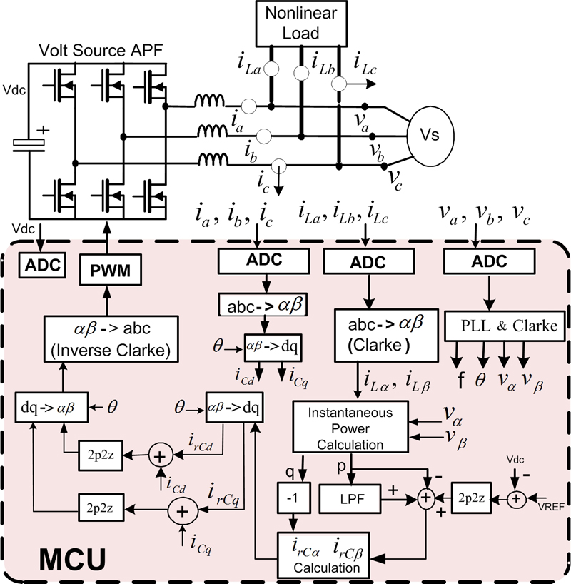
Figure 4 shows a shunt APF control implementation using an MCU. The voltage source APF injects 3-phase currents ia, ib and ic to cancel out the harmonic and reactive component of currents present in the non-linear load currents iLa, iLb and iLc. This improves the power factor and total harmonic distortion (THD) of the currents drawn from the 3-phase source Vs. The voltage and current loop digital controllers, indicated by the 2-pole 2-zero compensation (2p2z) blocks in the diagram, regulate the DC bus voltage Vdc and control the desired APF injected currents. In order to implement the multiple control loops, the on-chip analog-to-digital converters (ADCs) present in the MCU measure the line voltages (Va, Vb, Vc), the DC bus voltage (Vdc), the non-linear load currents (iLa, iLb, iLc) and the APF currents (ia, ib, ic).
Click image to enlarge
Figure 4. Shunt APF Control
As indicated in the Figure 4, the line voltages and the load currents are used to calculate the reference currents (irCd, irCq) for the APF current control loops. These reference currents are calculated for the stationary frame using the frame angle ϴ generated by the PLL block. The line voltages are used to implement this 3-phase PLL which provides the reference frame angle ϴ for the stationary frame. This implementation shows the pq-control method of determining the reference currents for APF current control loops.
The feedback current for the current-control loops are determined from the APF currents (ia, ib and ic). These 3-phase currents are first converted to equivalent αβ components using the Clarke transform and then to stationary reference frame components using the frame angle ϴ. The results of these conversions yield the current loop feedback currents (iCd and iCq) in the stationary reference frame. From the feedback (iCd, iCq) and reference currents (irCd, irCq), the error is calculated and passed to the current loop controllers. The current controller outputs are finally used by the on-chip PWM module to generate the PWM outputs for the APF inverter switches.
Speed is key
The complete control implementation uses multiple fast control loops and many trigonometric-intensive computations that necessitate a fast control-optimized MCU core with hardware accelerators such as TI’s trigonometric math unit (TMU) and CLA Real-Time Co-Processor. These accelerators combined with a fast CPU allow for faster control calculation and, hence, higher bandwidth current loops, resulting in a high-performance APF.
A fast 12-bit ADC equipped with flexible start-of-conversion (SOC) trigger scheme is also critical for such implementation. ADC SOCs are triggered at suitable points within the PWM cycle in order to achieve average current mode control. These trigger locations are selected to minimize the number of processor cycles between the time the ADC result is ready to the time it is actually read and used for control updates.
Similarly, these triggers can be placed accordingly to minimize the number of processor cycles between the time required for the control law (2p2z controller) to update the controlled parameter and the time at which the new control value actually takes effect. All these features imply an MCU with on-chip ADCs that are very flexibly tied to its PWM modules and the CPU, allowing flexible PWM trigger generation and subsequent fast interrupt loop execution.
The C2000 Piccolo TMS320F2807x MCUs from TI are an example of such a 32-bit floating-point MCU suitable for full digital control of APF. They use TI’s high performance C28x core and are further boosted by the TMU, which allows for expedited computation of math-intensive CPU instructions such as sine, cosine, and arctangent functions commonly used in APF applications. This improves performance of trigonometric-based algorithms and, hence, faster control loops. The F2807x MCUs also feature the real-time, programmable CLA, which allows the off-loading of time-critical control loop functions, thereby increasing the bandwidth of the main C28x CPU to focus on other system tasks, such as communications and system diagnostics.
F2807x MCUs use up to three 12-bit ADCs and eight windowed comparator subsystems (CMPSSs), allowing fast and accurate signal sensing and very fast, direct trip of the PWM outputs in overvoltage or overcurrent conditions. In addition, this MCU has three 12-bit digital-to-analog converters (DACs) and precision control peripherals such as enhanced pulse width modulators (ePWMs) with fault protection and eCAP (enhanced capture) modules for APF signal frequency measurement.
Looking forward
Non-linear load and switching of large power equipment introduces harmonics in currents and voltages and other power quality problems such as unbalance in phases, sags and spikes. Passive filters and active power converters are employed to correct, attenuate and or eliminate such power quality problems.