Improving efficiency and reducing costs in solar inverters
High-reliability SiC Schottky diodes can improve operating efficiency and reduce total cost of ownership
A niche market only a few years ago, the solar photovoltaic (PV) industry is now becoming a mainstream electricity provider, and changing the way the world is powered. Following a difficult period of industry consolidation and economic crisis, PV installations saw another record year in 2013, with more than 38 GW of newly added capacity around the globe (source: EPIA). Future forecasts, even under the most pessimistic scenarios, predict that over the next few years, solar PV is on the way to becoming a major part of the electrical system, delivering clean, safe and affordable energy to many around the globe (see Figure 1).

Click image to enlarge
Figure 1: Solar PV is on the way to becoming a major part of the
Solar panel basics
Simply put, a solar panel refers either to a PV module, or to a set of solar PV modules electrically connected and mounted on a supporting structure. A PV module is a packaged, connected assembly of solar cells. Solar panels can be used as a component of a larger PV system to generate and supply electricity in commercial and residential applications. Each module is rated by its DC output power under standard test conditions (STC), and typically provides up to 300 watts (W).
The efficiency of a module determines the area of a module given the same rated output. For example, an 8 percent efficient 230 W module will have twice the area of a 16 percent efficient 230 W module. There are a few solar panels available that exceed 19 percent efficiency. A single solar module can produce only a limited amount of power, and most installations contain multiple modules. A PV system typically includes a panel or an array of solar modules, an inverter and sometimes a battery and/or solar tracker and interconnection wiring.
Solar modules use light energy or photons from the sun to generate electricity via the PV effect. The majority of modules use wafer-based crystalline silicon cells or thin-film cells based on cadmium telluride (CdTe) or silicon. The structural load-carrying member of a module can either be the top layer or the back layer. Cells must also be protected from mechanical damage and moisture. Most solar modules are rigid, but semi-flexible ones are available, based on thin-film cells.
Bypass diodes protect solar arrays
Bypass diodes are fundamental protection elements required in a solar panel or array. Each string in the system is typically comprised of up to 20 series-connected solar modules, each with typically 72 cells that are, similarly, all connected in series. The result is a roughly 1,000-cell string, with each cell attempting to produce current in direct proportion to the amount of sunlight it sees. If any of these cells become shaded, or damaged, then the entire string current is limited to that which the weakest link can support. Besides being susceptible to temporary performance losses when even a single cell is shaded, an array constructed using long-series strings can introduce other, more subtle problems into a solar-electric system.
A typical silicon cell has a forward voltage of 0.5 volts (V) when optimally loaded, while thin-film processes such as CdTe or CIGS vary from 0.3 V to over 1 V. If, for some reason (such as shading), a cell cannot produce as much current as other nearby cells, then this same cell will now be forced into a reverse mode of operation where it is subjected to a negative voltage, which, depending on its position in the string, can be from 5 to 30 V.
Damaging heat
Although the cells are somewhat forgiving, if enough mismatches are present, the under-performing cell will be driven into the region of reverse breakdown. With up to 20 solar modules connected in series, the DC output of a modern solar system can easily be 400 V. Under these conditions, the shaded cell with 30 V applied across it may begin operating in reverse breakdown, with the functional cells in the rest of the string accounting for the remaining 370 V. In a typical system where string currents approach 10 Amps (A), a shaded cell is quickly transformed into a 300 W heating element, creating a hot spot that can easily damage the panel.
To prevent panel damage, or even a fire, solar manufacturers have traditionally arranged their panels into substrings of 12 to 24 cells, each with its own bypass path (see Figure 2). The decision to use 12- to 24-cell groups is based on a comparison of the summation of the forward voltages versus the expected breakdown voltage of the weakest cell in the string.
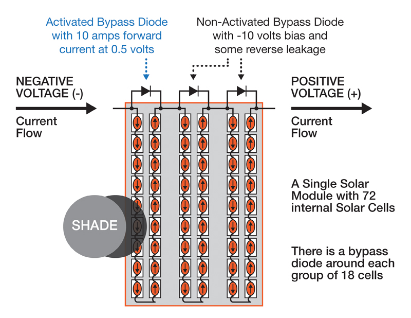
Click image to enlarge
Figure 2: Bypass Diode Operation in a Solar Panel
For example, in a group of 24 cells, each with a forward voltage of 0.5 V, an overall voltage of 12 V will be produced. To prevent a breakdown-induced “meltdown,” the bypass diode must be inserted at points that prevent the total number of diode drops that comprise the local loop’s voltage from exceeding an individual solar cell’s reverse breakdown threshold (which is usually 25 to 30 V).
It should also be noted that bypass diodes provide some protection against DC arcing, which can be very dangerous, as they will not self-extinguish. Arcing in AC systems often clears itself at the zero crossing of the 50/60-Hz waveform, while a DC-generated arc must be interrupted by a protection device or by physically moving the discharge points further apart. Bypass diodes can provide limited protection against “series” arcs within the module itself, because they limit the local arcing voltage to 10 to 20 V.
Solar inverter field reliability
A large European solar inverter manufacturer contacted Microsemi to discuss a problem it was experiencing with its incumbent supplier of SiC Schottky diodes, which were being used in its solar inverters. The solar inverters used a full-bridge configuration, utilizing four 1200V 10A SiC Schottky diodes per system.
The manufacturer reported that it was experiencing a 2 percent field failure rate which could be isolated to the SiC Schottky diodes. Field failure costs include both the cost of material replacement and the cost of the removal and assembly by a certified technician. The total cost is typically many times more than the cost of the module.
Microsemi worked with the solar inverter manufacturer to supply 5,000 high quality 10A SiC 1200V diode samples and performed a series of rugged laboratory tests, followed by six months of further testing in the customer’s field trial. Over two years later the Microsemi SiC Schottky diodes still show a zero percent failure rate. The reason for the significantly lower failure rates can be explained by Microsemi’s unique thin-film passivation technology.
Microsemi’s SiC Schottky diodes have been manufactured at Microsemi’s SiC wafer fabrication facility in Bend, Oregon since 2007 and they provide high reliability for two fundamental reasons. Some SiC Schottky diodes often apply the passivation layer during the post fabrication phase, whereas Microsemi applies thin-film passivation during the wafer fab process and uses a superior thin-film passivation chemical, which leads to higher reliability (see Table 1).
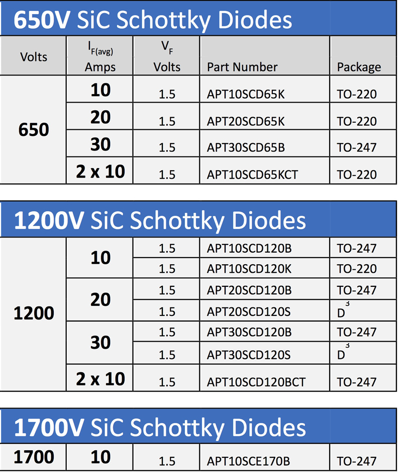
Click image to enlarge
Table 1: Microsemi’s SiC Schottky diode product line
The utilization of devices such as Microsemi’s SiC Schottky diodes for solar inverter applications will yield failure rates that could be significantly lower than expected failure rates of other manufacturer’s SiC Schottky diodes, resulting in very infrequent replacement of modules, and lower total cost of ownership (TCO).


