By combining FEA with FPGA hardware, simulation models can include nonlinearties for accurate motor representation
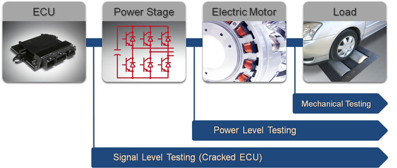
Figure 1: Each stage of embedded-software validation for electric-motor simulation introduces new challenges for test engineers such as high-speed processing and high-power signals.
The growing adoption of electric motors in the automotive industry creates new challenges for embedded-control-system developers and test engineers. Control algorithms for electric-drive ECUs (electronic control units) must run much faster than power-train ECUs for internal-combustion engines. These higher speeds make the traditional approach to HIL (hardware-in-the-loop) testing inadequate for testing electric motor ECUs. Engineers must simulate electric motors with high fidelity, and HIL test systems must be able to execute simulation models at rates on the order of 1 ?s to adequately represent the electric motor's operation (Figure 1). Power electronics introduce another challenge when developing and testing electric-motor control systems. To test the power electronics, the test system must handle voltages that range from 20 to 600 V and current that could be in excess of 500 A. These types of tests often implement on a dynamometer, but dynamometers are limited in the test coverage that they can provide. They often fail to represent accurately vehicle dynamics, which increases the number of field tests necessary to validate fully an electric vehicle power train. A test system capable of handling high-power signals while accurately simulating vehicle dynamics reduces the number of dynamometer and field tests, and reduces the overall time and cost to test.

Motor simulation using FEA One of the greatest challenges engineers face when conducting real-time simulation of advanced motor drives is how to attain an adequate combination of model fidelity and simulation step time. While a simple constant parameter D-Q model may be sufficient to conduct some HIL tests, increased model fidelity is often necessary for the design of advanced motor drives. High-fidelity simulation also applies to performance optimization of control systems in high-efficiency electric motor applications commonly found in the automotive industry. Using high-fidelity FEA (finite-element analysis) models, an engineer can simulate complex, non-ideal behavior such as cogging torque and design a controller to reduce torque ripple. Similarly, a designer can simulate the variation in motor inductance at high currents, which greatly affects the torque produced by the motor, and test the controller accordingly. Lower-fidelity models do not adequately represent cogging torque, motor inductances at high currents, or other nonlinearities in the simulation. The absence of these characteristics reduces the effectiveness of HIL testing, which results in more field tests and increased development time to test adequately embedded-control software. FEA is a simulation method that provides highly accurate motor models with enough fidelity to account for nonlinearities found in electric motors (Figure 2). However, historically, this high fidelity simulation has been limited to software-only implementation, because it can often take hours to simulate a few seconds worth of real-world operation. To perform HIL testing on electric motor systems, simulation models must run in real-time. High-fidelity models need simplifying to run within the limits of processor-based systems, resulting in reduced effectiveness of HIL tests. A processor-independent, hardware-based simulation is necessary to achieve the closed-loop update rates required for electric-motor HIL testing. FPGAs provide the high speed processing necessary for electric-motor simulation and high-speed update rates with low latency from input to output. However, because FPGAs are hardware, they have limited available resources. Engineers must often simplify electric-motor models to operate within the limits of these resources, which reduces model fidelity. To obtain the performance and accuracy necessary for real-time high-fidelity electric-motor simulation, an FPGA must be large enough to contain the entire characterization of the electric motor. Advancements in FPGA technology have made it possible for tools such as the JMAG add-on for NI VeriStand to perform real-time high-fidelity simulation of electric motors for HIL testing. Meanwhile graphical-programming tools such as LabVIEW FPGA provide an abstracted tool chain for FPGA development that reduces development time for creating high-fidelity electric-motor models.
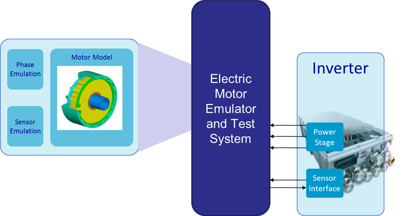
High-power HIL testing While signal-level testing provides much value for developing control algorithms and evaluating ECU performance, it is important to also validate the power electronics associated with the system. Dynamometers are common for power-level testing, but they cannot accurately represent high-frequency dynamics needed to adequately validate system performance. The lack of test coverage dynamometer testing achieves forces test engineers to perform extensive field tests, which results in reduced test coverage and higher overall test costs. An HIL test system capable of integrating power electronics and simulating vehicle dynamics provides test coverage not found in dynamometer testing. In the case of an electric-drive dynamometer, the original electric motor in the drive train couples to another electric motor that the test system controls. This electric-motor-dynamometer configuration involves an electric drive tested together with a controller that includes high-voltage power electronics. The problem with this procedure is that the rotating test system itself constitutes a drive train with drive shafts and load machine, but it has nothing in common with the vehicle into which the electric motor will eventually operate. This renders it almost impossible to model mechanical feedback and turning-speed dynamics from the vehicle with any level of accuracy. This is a serious disadvantage since electric-motor speed does not always couple to vehicle speed, especially in hybrid drives. In many real-world scenarios, there are intermediate states with gears disengaged and no drive to the wheels, which leaves the electric motor to turn without any load. The test system cannot reproduce the resulting turning speed dynamics in the rotating test system, because the inert masses involved are too different from those in the future vehicle. This forces engineers to test the ECU in a test vehicle on the road. An inverter test system, or electric-motor emulator, bridges this gap between the HIL test system and vehicle field tests (Figure 3). This system can interact with high-power signals associated with inverters, and it allows engineers to reproduce load and ambient conditions in the lab exactly as they occur in a drive inverter under field conditions. System level testing that accurately simulates real-world conditions helps test engineers find faults earlier in the embedded software development process, which reduces costs and minimizes development cycles while yielding test data of higher quality. In practice Real-time high fidelity electric motor simulation makes it possible to test many types of transient and fault conditions that would be difficult or impractical to perform with the real systems. In the past, many of these conditions such as faults on motor terminals or faults between DC and AC busses have been impossible to implement during HIL testing with standard DQ electric-motor models. By combining high-fidelity FEA with high performance FPGA hardware, simulation models can include complex non-linear behavior for accurate motor representation. The signals from the model running in FPGA can then connect to other hardware at the high I/O rates necessary for complete testing. Electric-motor emulators are useful at very early stages in developing and testing hybrid drives and other drives with electric motors. Engineers can map any electric motor type using an integrated emulator, which will behave like the corresponding physical motor in dynamic turning-speed operation. Emulators also allow developers to model phenomena not yet accounted for in controllers such as harmonic vibrations in electric motors and cancelling out acoustic effects in control engineering. The system runs like a physical motor, but without any moving parts. This means that engineers can run a wider range of tests and collect more accurate data, which reduces time spent with field tests and produces better embedded software. National Instruments SET GmbH


