Remote nodes need to be autonomous in terms of energy
A key consideration for wireless sensor nodes that will populate the Industrial Internet of Things (IIoT) is battery lifetime. The sensor nodes, in many applications, will need to be installed in locations that are difficult to reach and, consequently, service. Because it is too costly and difficult to run power lines to them or to have maintenance workers replace batteries regularly, these nodes need to be autonomous in terms of energy.
Along with low power consumption in the processing electronics, the battery itself must be able to support long service times: potentially as long as twenty years. Because of their self-discharge rate, many battery chemistries cannot support such a long service life, even when supporting specialized low-energy electronics.
However, Lithium thionyl chloride chemistry has a very low self-discharge rate. This chemistry provides the longest life and highest energy autonomy seen so far for primary battery technology suitable for IoT sensor nodes and other equipment where small size is important. Lithium thionyl chloride chemistry service life of the has been demonstrated over a period of close to forty years with AA-size cells having exhibited a service life of more than twenty years in utility meters.
Chemistry characteristics
As the applications for long-lifetime battery-powered systems widen, it is important to take into account the characteristics of the lithium thionyl chloride chemistry. With the addition of wireless communications to sensor nodes along with actuation functions – such as the ability to open and close gas or liquid valves – there is an increase in the peak current required from the battery.
In a typical sensor-node or metering application, the microcontroller will be asleep for much of the time, waking up to take readings at regular intervals to store them in local memory. At less frequent intervals, the microcontroller will wake-up the wireless communications module to send a packet of stored data to a gateway or server. The current needed may reach 500 mA when the wireless interface is transmitting. However, it only needs to be on for a period of a few hundred milliseconds.
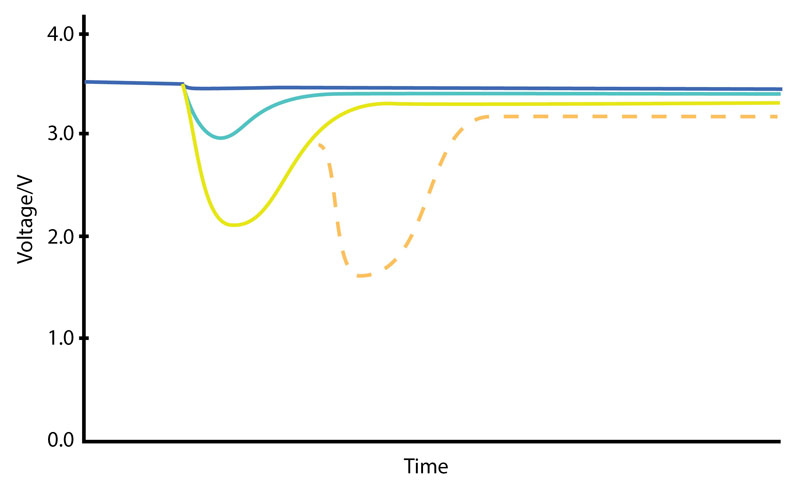
The inevitable effects of ageing can reduce the in-field lifetime of the battery although the nominal battery ratings may appear to support such short-term peak currents. The available capacity from the battery is affected by the self-discharge rate and by a gradual impedance rise caused by the generation of substantial current pulses (see Figure 1).
Click image to enlarge
Figure 1: The effects of different sized current pulses on battery voltage with time with the potential cumulative effect for successive pulses shown. The use of a constant low current will restore the voltage level.
The very low lithium thionyl chloride battery chemistry self-discharge rate is largely due to a passivation layer of lithium chloride that forms on the surface of the anode as it discharges. Although this insulating layer restricts current flow, it is partially dislodged by loading the cell. However, because of the chemical processes needed to form conductive paths through the passivation layer, there is a delay involved. This is exhibited as a transient voltage drop followed by a slow rise in voltage under constant load.
Depending on the thickness and density of the passivation layer, the magnitude of the transient voltage drop varies. The higher the discharge current, the lower the voltage supplied. There is a tendency for the amount of passivation to increase by partially discharging a cell and then removing the load. This increases the voltage reduction and delay each time.
For example, when discharging a D-size cell, such as the Tadiran TL-5134/P, gradually with a continual load of around 50 µA, it can be expected to continue to deliver current close to its nominal voltage over a period of more than ten years. However, the situation changes if the battery is required to deliver much larger current pulses. Using the same D-size cell and using it to deliver current pulses of 150 mA, experiments by Tadiran have shown that the same cell will sustain a voltage of 3 V for only around two years.
After that, the voltage begins to decline and gradually falls to 1.5 V after five years. In a circuit designed for an expected voltage of higher than 1.5 V, the battery appears to be fully discharged after five years and not ten or twenty. However, the battery still has plenty of stored charge and could continue to deliver the energy required for another ten years if the system was designed to harness it.
The key to continued long service life with a lithium thionyl chloride cell is smoothing out the current demand so that the cell is not expected to deliver any large current pulses. This requires the use of an energy-buffering scheme that delivers pulses of energy while the battery provides a constant stream of charge into the buffer circuitry.
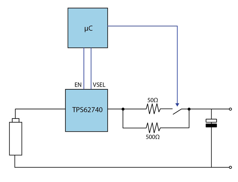
One way to provide a controlled energy buffer is to employ a large capacitor and a DC/DC converter, such as the Texas Instruments TPS62740, to regulate the flow of the charge into the capacitor. A double-layer capacitor or supercapacitor would be a suitable choice to ensure that there is enough charge to operate a wireless link for several hundred microseconds (see Figure 2).
Click image to enlarge
Figure 2: The use of a microcontroller with the TPS62740 to control the voltage supplied to a supercapacitor.
The circuit design uses a resistor on the output of the DC/DC converter to limit current flow into the supercapacitor and, with that, the current drawn from a high-capacity primary cell such as those found in the Tadiran XTRA series. The resistor selected needs to keep the current demand at a level consistent with long service life. Although it is possible to directly connect the primary cell to the capacitor through a resistor, the advantage of using a DC/DC converter its output voltage can be adjusted dynamically to minimize energy losses from the resistor.
As the supercapacitor charges towards its maximum capacity, a programmable DC/DC converter, such as the TPS62740 can, increase its output voltage incrementally. A suggested profile is an increase of 100 mV every 30 or 60 seconds. The overall charging period may be over the period of ten or more minutes. However, during this time, because of the gradual step up in supply voltage, the drop across the resistor will always be less than 100 mV. Although the current demand from the battery rises sharply before decaying away on each step up in voltage, the current demanded is on the order of 2 mA to 4 mA, which does not adversely affect internal resistance too much.
Two factor will limit the voltage range over which the DC/DC converter will supply charge – the voltage required by the microcontroller supplied downstream from the capacitor and the maximum voltage of the supercapacitor, which is typically in the 2.5 V to 2.7 V range. An embedded microcontroller may expect to see a voltage range from 1 V to 2 V. As a result, the DC/DC converter will have to operate over a range from 1 V to 2.7 V, possibly narrower depending on the microcontroller and supercapacitor choice.
At start-up, the supercapacitor will need to be charged to the voltage level expected by the microcontroller. For this stage, a larger resistor may be used to properly limit current flow into the supercapacitor (as shown in Figure 2). Upon reaching the initial target voltage, a smaller resistor can be switched in to minimize overall losses. This can be achieved by arranging the two resistors in parallel. A normally open switch operated by the microcontroller ensures that the use of the higher resistance during start-up. After the target voltage level is reached, the microcontroller switches in the lower resistance path.
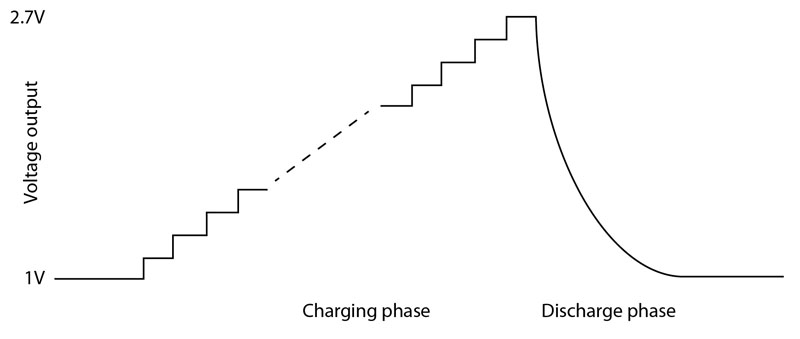
The switching conversion in the DC/DC converter combined with the current-limiting resistor results is some losses. However, the stepped operation helps keep overall efficiency close to 90%. The result of this power-control strategy is a circuit that maximizes the lifetime of the lithium thionyl chloride battery cell (see Figure 3).
Click image to enlarge
Figure 3: The use of a gradually stepped voltage during charging followed by a discharge cycle when the radio module is active.


