Measuring and sourcing DC transients and other DC test conditions

1. Biasing with a static DC voltage and measuring current: This is the most basic application of DC power related bench instruments. Any power supply, so long as it has the right voltage and current ratings, can be set up to provide a static DC voltage. Most supplies have built-in ammeters to measure static DC current. In those instances where better measurement accuracy is needed, a DMM can be used, but they are limited to currents of 5 A or 10 A. 2. Setting up turn-on/turn-off sequences: Many devices today require multiple DC bias voltages to operate properly, and these devices often need a particular, controlled turn-on sequence. It is nearly impossible for you to manually turn on multiple power supplies with precise timing, which means that you must use a computer and write a program to sequence the supplies on in the right order and with the right timing. (See Figure 1)
3. Measuring and displaying current versus time to visualize power: During dynamic events, such a motor pulling a peak of startup current, it is desirable to visualize the flow of current versus time. An oscilloscope is an ideal tool for measuring voltage versus time, but scopes cannot directly measure current. Current probes are commonly used, but need to be calibrated before use and drift significantly during use, yielding unrepeatable, imprecise measurements that may not be trustworthy (Figure 2).
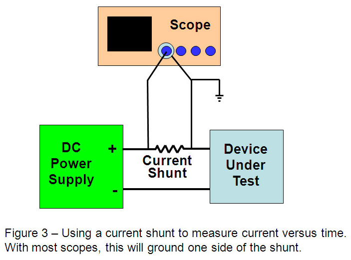
Alternatively, a current shunt (aka current sense resistor) can be used, but to get an accurate measurement you need to precisely know its resistance value. As current flows through the shunt, the shunt will heat up and change value, so it is difficult to accurately make this measurement because the shunt value is changing. Most scope inputs are ground referenced, so when you connect the scope across the shunt, you are grounding one side of the shunt, which could cause an undesirable grounding issue. Selecting the right resistance value is another challenge. If the resistance is too high, as high current flows through the DUT, there could be an unacceptably large voltage drop across the shunt, called its burden voltage. With high peak currents typically found in motors and machinery, you will need to use a very low resistance shunt to keep the voltage low during the current peaks. Then, it will be difficult to measure the normal operating current of the device because the voltage drop across the shunt will be too small for the scope to accurately measure. (Figure 3)
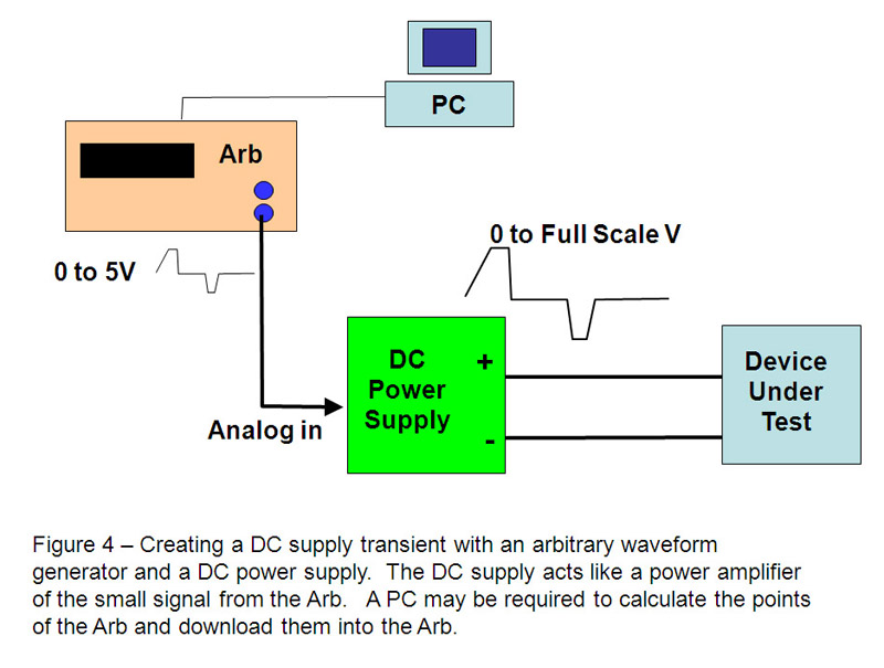
4. Generating DC bias supply transients and disturbances: When characterizing a design or troubleshooting fault conditions, you will want to subject the design to a variety of conditions to see how the device responds. High transient currents found during motor startup or machine turn-on can wreak havoc on nearby sensitive systems, so it is important to be able to recreate these transient conditions and look for problems they may cause. To generate these conditions, you would turn to an arbitrary generator to create a modulation waveform and then use that waveform to drive a powerful DC power supply to generate the transient - provided the DC source has an analog programming input that can be driven by the Arb. And is the DC source fast enough to track the Arb and create the waveform? To create these transients, you will probably end up building a mini-test ATE system to program the Arb, drive the power supply and measure the resultant behavior of the DUT. (Figure 4) An Alternate Solution for DC Sourcing and Measurement Tasks A different approach is the DC Power Analyzer, which combines the capabilities of four power supplies, voltmeter/ammeter, scope, arbitrary waveform generator, and datalogger in a package that fits nicely on the bench. Thus, the DC Power Analyzer offers an alternative to a collection of standard bench instruments. A DC Power Analyzer eliminates the need for multiple pieces of equipment and complex test setups. All of the measurements and functions are available right from the front panel, so it also eliminates the need to develop and debug test programs. As a result, it provides engineers the ability to setup tests and make measurements. And since all functions are integrated into a single instrument, it is fully specified so the engineer can have confidence in the performance of his test equipment. Let's look at those four tasks again and how a DC Power Analyzer could handle them: 1. Biasing with a static DC voltage and measuring current: The DC Power Analyzer's most basic function is to provide DC voltage and current, like any other power source. But if your needs are only for simple, static DC bias, the trusty power supply on your bench right now is quite capable; the DC Power Analyzer would be overkill. 2. Setting up turn-on/turn-off sequences: The DC Power Analyzer can sequence the turn on of its 4 DC power supplies. Turn on/off delays between outputs can be set directly from the front panel with delay times. 3. Measuring and displaying current versus time to visualize power: The DC Power Analyzer has a built-in scope function that can directly measure the current versus time flowing out of its power supply into your device. There is no need for a current probe or a current shunt, so all of the measurement challenges associated with the transducer are eliminated. 4. Generating DC bias supply transients and disturbances: In the DC Power Analyzer, the built-in arbitrary waveform generator's only job is to modulate the DC power supplies. Canned waveforms, like sine, staircase, and pulse, are available. User defined waveforms are also supported so it is easy to create DC supply transients to simulate real world power disturbances right from the front panel of the DC Power Analyzer. Furthermore, the DC Power Analyzer can make voltage transitions in as fast as 160 microseconds. This means that narrow pulses and other fast events can be faithfully produced. A demanding task As DC bias tasks become more sophisticated, involving sequencing and dynamic sourcing and measurement, traditional instruments start to fall short. These tasks will require complex interaction of several instruments and transducers, causing setup and configuration challenges. Often, a PC is used and software must be written to orchestrate tasks that are too complicated for a person to manually execute. All of this adds up to a lot of setup time to make the required measurements. Agilent Technologies


