This is largely because of the increased adoption in applications where thermal management, output and accuracy must be balanced
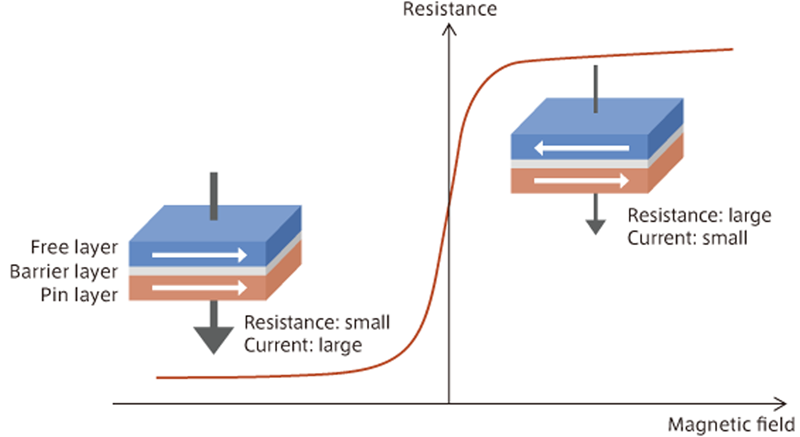
Figure 1. Principle of TMR
As the magnetization directions of the pin layer and free layer are parallel, the resistance becomes small and current flows with little resistance. When the magnetization directions of the pin layer and free layer are not parallel, resistance increases which limits current flows.
Tunnel-magnetoresistance (TMR) elements for sensors has become increasingly popular over the past few years. This is largely because of the increased adoption in applications where thermal management, output and accuracy must be balanced. Initially used for consumer electronic applications such as mobile devices where thermal management is critical, they are now being adopted more for automotive and e-vehicle applications and industrial equipment applications. As a result, TMR sensors have become an important part of self-driving cars.
Prior to the rise of TMR sensors, anisotropic magnetoresistance (AMR) and giant magnetoresistance (GMR) sensors were used in applications where thermal controls were required. Each varies in terms of output and thermal management, but TMR sensors are typically more accurate and are therefore experiencing significant adoption and focus from manufacturer R&D teams seeking to refine and further improve TMR sensors.
TMR sensor technology
One such innovation is combining a TMR element, which is a highly-sensitive reproducing element of an HDD head, with a new type of magnetic sensor. The reading elements of HDD heads have been used since the 1980s to improve the recording density of HDDs. The technology has been incorporated into various sensors for years, but as the technology has matured, it can be used with greater efficiency.
In the case of TMR sensors, as change in resistance is caused when an external magnetic field is introduced to the application, changing its direction. In a TMR element, the current flows perpendicular to the film surface, making its magnetic structure unique among magnetoresistance sensors. In an AMR or GMR element, the current flows horizontally to the film surface, which is significantly different and may be used to refine current control.
The structural differences don’t end there. A TMR element consists of two ferromagnetic layers (free layer/pin layer) that lie on either side of a thin-film element containing a barrier layer made of a thin insulator of 1 to 2nm, created through advanced thin-film processing technology.
While the direction of magnetization within the pin layer is fixed, the direction of magnetization within the free layer changes as an external magnetic field is applied. The direction of this external magnetic field creates electrical resistance of the TMR element, which then will change according to the magnetic change in the free layer.
Consequently, there is minimal electrical resistance when the magnetization directions of the pin layer and free layer are parallel, allowing a large current to flow into the barrier layer. If the magnetization directions are forced not to be parallel by the external magnetic field, the resistance increases and current flows stop flowing into the barrier layer.
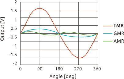
The outcome is staggering when a magnet is rotated in a TMR sensor. Improvements have been shown to provide as much as 20x the output of AMR sensors and 6x the output of GMR sensors. This is because the magnetization direction of the free layer follows the magnetic field direction of the magnet, and the resistance of the element correspondingly changes. Significant output is realized when highly-sensitive TMR elements are used as magnetic sensors. These characteristics are the reason why TMR elements are employed as highly-sensitive reading elements in HDDs.
The change in resistance is explained by a MR ratio value. The MR ratio of a conventional AMR element is as high as three percent. For a GMR element, the MR ratio is 12 percent. The MR ratio of a TMR element is a full 100 percent. This is largely because electron transfer occurs as a quantum mechanical tunnel effect in TMR elements. When the pin layer and free layer are antiparallel, a TMR element has such extreme characteristics so that electrons will not move. This is why TMR elements have a large MR ratio.
In addition, since the resistance value of the element is proportional to the relative angle between the magnetization directions of the pin layer and free layer, it can be used as an angle sensor that performs 360° angle detection.
Some TMR sensors have extremely low power consumption (5mW/under recommended conditions). This makes them ideally suited for automotive applications, including as automotive steering angle sensors or EPS (electric power steering) motor angle sensors where low temperature drift is required.
When AMR sensors are used, angle errors may occur when temperatures are too cold or too hot. Therefore, TMR sensors should be used to maintain consistent angle accuracy regardless of temperature range. For example, an angle error of ±0.6° or smaller in the magnetic field range of 20 to 80mT and the temperature range of -40 to 150°C is typical for a TMR sensor.
Click image to enlarge
Figure 2. Comparison of the characteristics of magnetic sensors using an TMR element, GMR element, and AMR element when a voltage of 5 V is applied.
TMR sensors can also improve an automobile’s fuel efficiency. Crank angle sensors or cam angle sensors in engines determine the optimal timing to inject fuel as well as the amount of fuel needed based on what they measure within the engine electronic control unit (ECU).
Cam angle or crank angle sensors and non-contact type magnetic sensors have enjoyed wide adoption, ad they are highly reliable and rarely show signs of wear or dust damage, resulting in a long life. Toothed-gear pulsar rotors that are made of a magnetic material are attached to a crankshaft or cam shaft, and a magnetic sensor to which a magnetic field applied by a bias magnet is placed to face it without contact. As a result, when the engine starts and the gear pulsar rotates, the density of the magnetic flux from the magnet changes. The magnetic sensor (tooth gear sensor) identifies this as a pulse signal, and detects the speed of rotation based on the volume of pulses within a specified timeframe.
TMR sensors have a very high output and sensitivity, compared to sensors using a hall element, resulting in better sensing capability for ABS (anti-lock braking) systems’ wheel velocity sensors. These sensors can be applied as current sensors that save energy by controlling charging and discharging of batteries.
Conclusion
As demand for magnetic sensors increases for automotive electronic equipment, so does the focus to improve the technology by manufacturers. The required efficiency of detection accuracy within automotive sensors must double that of conventional sensors, to realize safer automobiles. TMR sensors are unique in featuring high output, high accuracy, and low temperature drift and low aging deterioration to meet severe and tough market requirement.
Because to these characteristics, TMR sensors will continue to enjoy wide adoption.
TDK Corporation


