Passive Components in Modern Switched-Mode Power Supplies
Although the design of modern switched-mode power supplies is often characterized by newer technologies, passive components are still critical to their operation
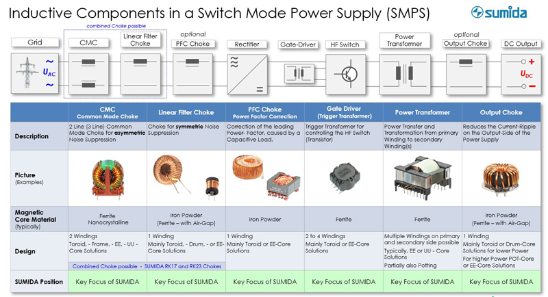
Figure 1: Sumida covers all inductors for switched-mode power supplies and partially and fully implements application-specific components
The high-frequency (HF) transformer and other inductors form the core of a switched-mode power supply (SMPS). Located in the input section, the interference suppression components ensure suppression of interference voltages and currents on the power supply lines.
Current-compensated chokes (common-mode chokes) suppress asymmetrical interference present on both lines in common mode. They are typically constructed with high-permeability ferrite cores or nanocrystalline core materials.
Linear filter chokes or differential mode chokes attenuate symmetrical interference. Most models have an iron-powder toroidal core or a ferrite EE core with an air gap, but open core designs such as bar or thread chokes are also possible.
In some cases, common-mode and differential mode chokes are combined into one component. In this case, the leakage inductance of the common-mode choke assumes the function of the differential mode choke; a magnetic bypass can act as an amplifier. Sumida’s RK17S and RK23S series are examples of this combination.
Optionally, power factor correction (PFC) chokes can be added to the suppressor chokes to provide sinusoidal current consumption for power factor correction. Like the chokes, the active PFC stages contain either iron powder or ferrite cores with an air gap to smooth the output current.
Gate driver transformers are used to drive the power transistor. Typically based on smaller ferrite core geometries than the chokes, they are characterized by low winding and coupling capacitance and low leakage inductance. Normally, they are rated for isolation voltages ranging from 1.5 kV to 5 kV and are available in THT or SMD versions.
Power transformers made of ferrite cores are the heart of a switched mode power supply. They ensure power transfer from the primary to the secondary side of the power supply. They are also responsible for the safe galvanic isolation of the primary and secondary sides. Since the output side of the power supply is often open, this isolation is required by safety standards.
Proven soft magnetic and low-loss materials with high saturation flux density are used for the power transformers. Their size is reduced as the switching frequency of the power supply increases.
Customized Inductors
In addition to standard inductors, application-specific ones are also available. For power transformers, for example, these are models with several different output voltages. Sumida specializes in this area. These can be variants of existing components that are tailored to a customer’s specific application based on standard pre-materials and existing technologies. Standardized core shapes and magnetic materials and standard plastic components are also used. For this purpose, Sumida can partly rely on its own MnZn and NiZn ferrites as well as iron powder cores.
Increasingly, however, there are requirements that can only be met with completely customer-specific components based on new magnetic core geometries and, in some cases, even new magnetic material compositions, proprietary plastic parts, and new manufacturing technologies.
Capacitors
Capacitors perform many functions in switched-mode power supplies. AC capacitors on the mains side (primary side) are mainly used to suppress or filter interference pulses. Ceramic or film capacitors can be used for this purpose. When they are connected between phase and neutral, it is important that they are X2 or X1 certified. For the connection between phase and protective conductor, a Y classification is mandatory. Since this provides greater electrical and mechanical safety than X capacitors, short circuits cannot occur due to a capacitor malfunction, for example.
Since X capacitors are connected between phases or neutral conductors, they do not have the same high safety requirements as Y capacitors.
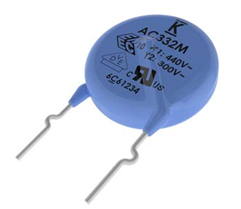
X and Y capacitors are further subdivided into different test/pulse voltages according to the requirements of IEC 60384-14 and are referred to as X2 and X1 or Y2 and Y1 types. The most common combinations are X1Y2 and X1Y1.
In addition, test marks such as ENEC, VDE, UL, or CQC can be found on most X and Y capacitors, since the components must be tested with regard to these standards.
Click image to enlarge
Figure 2: X-Y capacitors usually carry one or more test marks as shown in the photos
Robustness of Film Capacitors
Those who choose film capacitors should check if the application requires an increased temperature-humidity-biased (THB) class. This ensures that the capacitors are sufficiently robust against moisture – and therefore corrosion – to ensure the desired service life of the application.
The temperature-humidity bias test is a recognized standard for accelerated life testing. It involves accelerating the aging process of capacitors and measuring in two different tests whether they maintain their capacitance, dissipation factor, and isolation resistance at a given temperature, relative humidity, and nominal voltage over a defined period of time. Three levels (grades) are distinguished.
Because of the relatively small capacitance values usually required, ceramic capacitors are mainly used as Y capacitors in a value range of between 10 pF and 4.7 nF.
In addition to the classifications mentioned so far, capacitors are also differentiated according to their target application (commercial, industrial, or automotive) and according to their design.
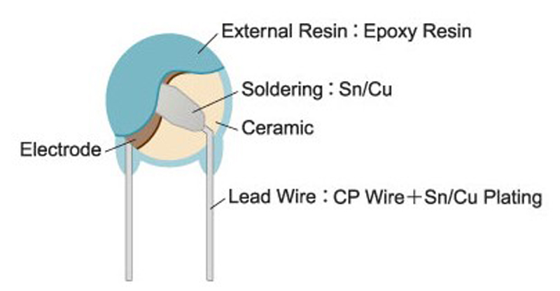
In terms of design, radial types as single layers are the most common and best known. These are ceramic single disks with spacing of 5 and 7.5 mm for X#Y2 and 10 and 12.5 mm for X#Y1 versions (Figure 3).
Click image to enlarge
Figure 3: Structure of a radial single-layer capacitor
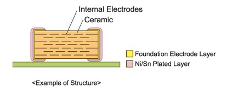
In addition, many SMD types are now available as X2, Y2, or X1Y2 versions as multilayer ceramic capacitors (MLCC) and Y1 or X1Y1 versions as single-layer plastic-molded leadframe for surface mounting. Compared with the leaded, radial versions, these offer advantages above all in terms of smaller volume and lower overall height as well as higher suppression levels with the same capacitance values (Figure 4).
Click image to enlarge
Figure 4: Section through an MLCC
In switched-mode power supplies, a high-voltage electrolytic capacitor is typically used as a buffer downstream of the AC filter on the input side and the first rectifier. Models with a low ESR and a long service life are recommended for this purpose.
On the secondary side, too, low capacitor ESR is also a priority. This allows high output currents and minimizes the residual ripple of the output voltage as much as possible.
Resistors
Among other things, resistors are used as bleeder or leakage resistors and as pre-charge resistors, for protection against overvoltages and overcurrent, and for current measurement.
The bleeder resistor is used to discharge the capacitor, as this could otherwise cause an electric shock even when the power supply is switched off. It is not absolutely necessary in regulated low-voltage power supplies, and it is not needed in linear voltage regulators or switched-mode power supplies with fast duty cycle control to maintain a constant DC voltage.
Axial, leaded safety resistors are typically used as pre-charge resistors for the buffer capacitors. This is because they bring low resistance value and high pulse strength.
In addition, resistors are used to detect the phase position of the AC voltage to achieve a more accurate divider ratio. Thin film MELF resistors with outstanding pulse load capability and flat chip precision resistors in thin film technology are suitable for this purpose.
Overvoltage metal oxide varistors “clamp” overvoltages to protect the non-inverting input of the comparator. Thanks to their halogen-free, high-temperature-resistant silicone coating, they operate at an operating temperature of up to 125 °C and have a maximum current-carrying capacity of 13 kA.
When powerful loads are switched on, very high currents occur for a short time, which can cause damage to the system. PTC and NTC thermistors are used as switch-on current limiters or overcurrent protection. They can also be used for temperature measurement since their electrical conductivity changes as a function of temperature.
The easiest way to limit high switch-on currents is to use low impedance power resistors. In normal operation, however, a relatively high-power loss occurs at these resistors. For this reason, the use of NTC or PTC thermistors is recommended. When combined they offer the greatest advantages.
The most important selection criteria for the NTC thermistor are the maximum current and the nominal resistance (R25). The latter must be at least large enough, by circuitry in series with the load, to limit the current to a value that will not blow the fuse and cause damage to other components. The maximum current is determined by the power of the load. The derating of the NTC thermistor must also be taken into account.
PTC thermistors are suitable for safe current limiting with high-capacitance capacitors in DC intermediate circuits. Due to the high current flow, they heat up and become highly resistive and thus intrinsically safe. As a result, they limit the current to safe values in the event of a short circuit in the DC intermediate circuit. They are designed for DC voltages of 260 to 560 V, offer resistances of 22 to 1100 Ω at 25 °C, and, depending on the type, have UL, IECQ, and VDE approvals as well as AEC-Q200 qualification.
Another application of resistors in switched-mode power supplies is current measurement. Low impedance shunt resistors are used for this purpose.
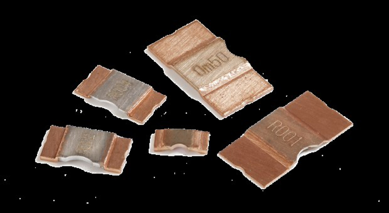
Click image to enlarge
Figure 5: Resistor elements made of solid metal are suitable for current measurements


