Isolation requirements for equipment
LTM2881 2.5kVRMS isolated RS485 μModule transceiver
An important consideration when designing medical products is satisfying the IEC 60601-1 safety standard and the isolation ratings for products that come into contact with patients. One of the most critical aspects of human safety and a challenging part of the product design is minimizing patient leakage currents, including AC currents. Since an isolation barrier always presents capacitance, it frequently must be minimized to limit AC leakage currents that result from signaling and switching supply voltages which induce capacitive currents. The most stringent leakage requirement is patient leakage from an applied part such as a floating cardio, type CF, applied part, for example an Electrocardiogram (ECG/EKG) probe pad. In normal operation the combined AC/DC leakage current must be less than 10μA. Patients and operators must also be protected from leakage paths from an enclosure or accessible parts of the equipment. These currents that a patient or operator may be exposed to are known as "touch currents." Under normal conditions, the touch current from or between parts of the medical system within the patient environment shall not exceed 100μA. This touch current limit is 500uA during a single fault condition (SFC), which occurs when a single means of protection is defective or a single abnormal condition is present. Medical electrical equipment shall have two means of protection (MOP) to prevent applied parts and other accessible parts from exceeding leakage and touch currents. A MOP includes insulation, air clearances, creepage distances, impedances, and protective earth connections. There are two fundamental classes of medical electrical equipment. Class I refers to electrical equipment that includes basic insulation plus additional safety protection provided for accessible parts to be protectively earthed / grounded. Class II ME equipment includes protection against electric shock from not only basic insulation but includes additional safety protection by double or reinforced insulation. There is no requirement for protective earthing or reliance on installation conditions to meet the class II safety requirements. Double insulation comprises both basic insulation and supplementary insulation. Double insulation provides two means of protection and reinforced insulation is a single insulation system that provides two means of protection. To satisfy two means of patient protection (MOPP) the component must be subject to AC test voltages. With a 5kVRMS rated component using solid insulation this translates into 707VPK or 500VRMS working voltage. There is a common perception that medical isolation devices must satisfy a minimum distance through insulation of 0.4 mm thickness. The other acceptable criterion is that the insulation must comprise at least two layers of material, each of which will pass the appropriate dielectric strength test. For reinforced insulation the appropriate dielectric strength test must be sufficient for two means of protection (MOP). IEC 60601 specifies patient leakage currents when equipment is connected to the patient with limits as low as 10μADC for normal operation and 50μADC for a single fault condition. The safest patient applied parts are F-type isolated (floating) applied parts in which the patient connections are isolated from other parts of the ME equipment. The isolation must prevent any current higher than the allowable patient leakage current to flow even if an unintended voltage originating from an external source is connected to the patient, and thereby applied between the patient connection and earth. F-type applied parts are further classified as either type BF for body applied floating or CF for cardio type floating. See Table 1. The table includes individual applied part currents as well as total patient leakage current which is a measure of the leakage current when all applied parts required for the operation of the medical device are in contact with the patient.
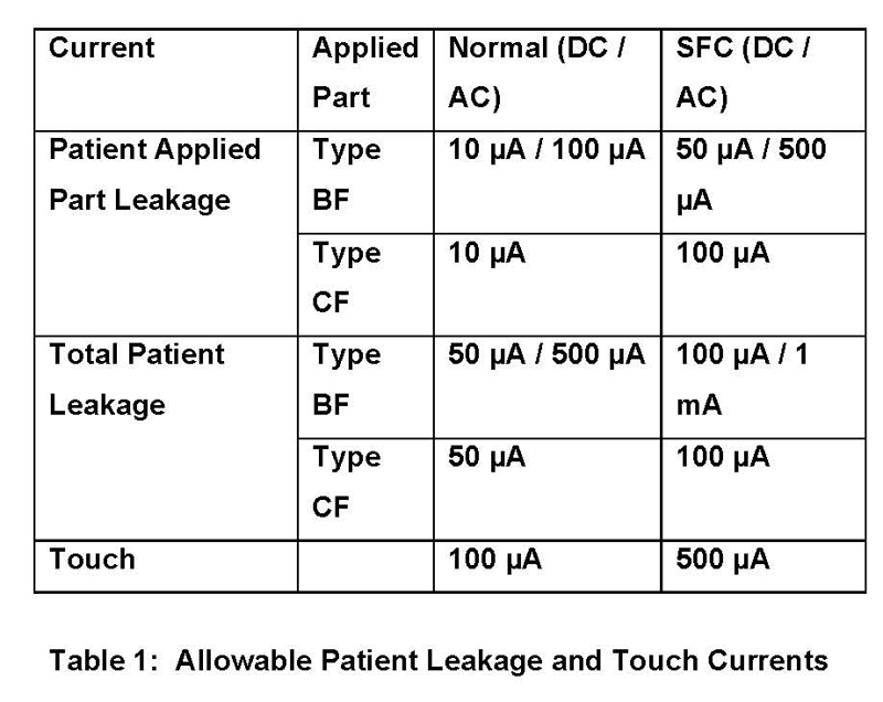
Touch current, also listed in Table 1, is a leakage current flowing from the enclosure or from equipment parts, excluding patient connections, accessible to any operator or patient in normal use, through an external path other than the protective earth conductor, to earth or to another part of the enclosure. The meaning of this term is the same as that of "enclosure leakage current" and is now aligned between IEC 60601 and IEC 60950 and properly reflects the fact that the leakage applies also to parts that are normally protectively earthed. Per the IEC60601-1 standard, components on the isolation barrier that satisfy two means of patient protection need to meet 4kVRMS isolation for a period of 1 minute. This standard also defines means of patient protection (MOPP), which describes the isolation protection required to reduce the risk of electric shock to the patient. There are also requirements for means of operator protection (MOOP). ME equipment requires two means of protection to reduce the electrical risk to the patient and the operator when a fault or failure bypasses one means of protection. The isolation protection requirements include the creepage/clearance distances, insulation and protective earth connections, pollution degree and total leakage current specifications. Two MOPP requires double the creepage distance and air clearance. Many ME products are powered from standard 120VAC as well as 240VAC and this standard working voltage is usually rounded up to 250VAC. The required creepage distance for one MOPP is 4mm and two MOPP is 8mm. This 250VRMS is equivalent to 354VDC (or peak) and requires a test voltage for two MOPP equal to 4kVRMS. As shown, 4kVRMS is a common isolation requirement for a patient-applied part to directly satisfy two MOPP. There is an additional, optional requirement that can apply to many medical instruments to stand off voltage up to 5kVPK, which reiterates the need for 4kVRMS. This is when the medical equipment and applied parts need to be defibrillation-proof. A defibrillation-proof applied part is where the part is protected against the effects of a discharge of a cardiac defibrillator to the patient. A defibrillator is basically a charged capacitor in series with an inductor to limit the current. This makes a decaying sine wave when fired and the peak voltage of the first ring can be significantly higher than the charge on the capacitor itself. It has been determined and agreed to in IEC 60601 that 5kVPK is the maximum value of this voltage overshoot, so that is what is required to keep the patient safe from electric shock if an isolation barrier were to breakdown when they are defibrillated.
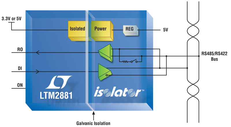
This type of design environment is extremely challenging. Meeting the requirements of IEC 60601 is required when developing products for medical markets. Linear Technology offers an expanding line of isolation devices that help meet the requirements for medical isolation. Linear Technology are introducing a line of 5kVRMS isolation devices offering integrated power to deliver up to 1Watt plus isolated data interface with no external components required. This family is based on the LTM2881 2.5kVRMS isolated RS485 μModule transceiver that provides uninterrupted communication through high voltage transient events at speeds of up to 20Mbps. The product includes an isolated 1W DC/DC converter with up to 62% efficiency, offering surplus power at a 5V regulated output. Everything from decoupling caps, diodes and even a switchable termination resistor are integrated into the module. The isolation barrier is constructed with two layers of dielectric material capable of up to 5kVRMS, which will meet the creepage and clearance requirements of the specification. The LTM2881 offers �15kV of ESD protection on the transceiver pins and across the isolation barrier.
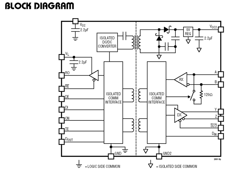
A superior failsafe receiver guarantees the receiver output to be in a logic-high state when the inputs are shorted, left open, or terminated, but not driven. The receiver thresholds are balanced to maintain data duty cycle with long network connections. The LTM2881 also protects itself by disabling the driver and receiver outputs in the case of excessive power dissipation. Meanwhile, a 1.62V to 5.5V logic supply pin makes it convenient to interface to digital components, while still maintaining TIA/EIA-compliant RS485 signals with either a 3.3V or 5V supply. The LTM2881 also offers a low current shutdown mode, drawing less than 5μA when not required to communicate. These new devices offer a robust solution that provides continuous communication, even through transient events greater than 30kV/μs. The LTM2881 offers a low EMI solution, with nominal barrier capacitance of 6pF, and can meet the requirements of EN 55022/CISPR 22 Class B radiated emissions provided good layout practices are followed. RS232 and digital logic isolator versions are also available. www.linear.com


