Role of the SAR ADCs in an industrial DAS
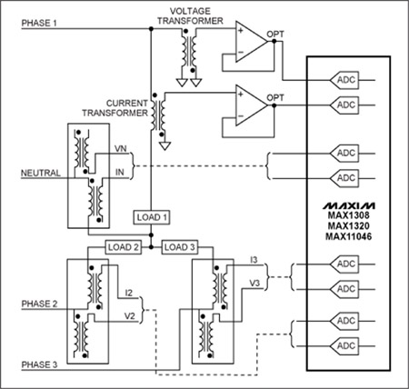
Many advanced industrial applications use high-performance multichannel data acquisition systems (DASs) to manage real-time information from precision industrial sensors. These complex systems require the use of high-performance, simultaneous-sampling, multichannel ADCs. Consider an advanced three-phase power-line monitoring/measurement system shown in Figure 1. Such a system requires accurate simultaneous, multichannel measurement over a wide dynamic range - up to 90dB (depending on the application) - at a typical sample rate of up to 64k samples/s. To optimize system precision, signals from the sensors (CT and PT transformers in Figure 1) should be properly conditioned to meet the ADC's input ranges and ensure that the DAS's characteristics will enable measurements that comply with international standards.
As Figure 1 illustrates, devices such as the MAX11046, MAX1320, or MAX1308 (or similar devices from other vendors) simultaneously measure the three phases and a neutral (voltages and currents). Each of these ADCs is based on a successive-approximation-register (SAR) architecture. These ADCs offer both a fast conversion time (up to 250ksps per channel for up to 8 channels) that allows the system to perform instantaneous measurements, and flexible input interfaces of �10V, �5V, or 0 to 5V to meet multiple application requirements. Some key typical characteristics of Maxim's SAR ADC families are shown in Table 1; competitive solutions from other vendors offer similar characteristics.
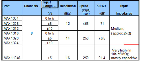
Typically, the outputs of the CT and PT (sensor) transformers are �10VP-P or �5VP-P. As Table 1 shows, the MAX130x and MAX132x ADCs cover these ranges well. The MAX11046's input range covers only one of the transformers' popular input ranges, �5V. The MAX130x and MAX132x ADCs have relatively low-impedance input circuitry. Consequently, for a power-grid monitoring system, these devices require an input buffer and low-pass filter (Figure 2a) to achieve 12-bit to 14-bit accuracy.
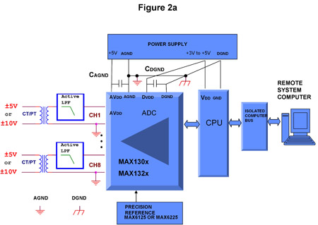
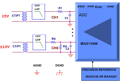
Figure 2: Board-level block diagram of a typical power-line monitoring application using the MAX130x and MAX132x families (a). Changes in the front end for an application using the MAX11046. A �5V transformer interface is used for channel 1 and �10V interface is set up for channel 8 (b) Active low-pass filters are required to interface to CT and PT transformers. An active-input buffer/low-pass filter is optional for MAX11046. The very high input-impedance values of the MAX11046 devices allow direct connection to specific sensors (see Table 1). The CT and PT measurement transformers, for example, represent relatively low-impedance sensors (i.e., effective impedance, RTRANS, is in the order of 10? to 100?) and, therefore, could be connected directly to the MAX11046 inputs using a simple RC analog front-end (AFE). If the 50Hz/60Hz signal in the measurement bandwidth has low levels of aliasing interferences, then a filter created by an input RC circuit can suffice. A simple and cost-effective approach to accommodate �5V or �10V ranges for the MAX11046 is shown in Figure 2b. Let's examine the input circuit in Figure 2b. You should pay special attention when selecting the values for R1, C1, Rd and C2. The 1:1 ratio resistive divider (Rd1 = Rd2 = Rd) represents a load for the PT and CT transformers, which will cause gain error. This gain error can be calculated using Equation 1: Gain error % = (1 - 2 × Rd/(2 × Rd + RTRANS)) × 100 (Eq. 1) Where: Rd is the divider impedance; RTRANS is the transfer impedance; The effects of the resistance values on the gain error are shown in Table 2.
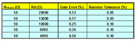
Data from Table 2 demonstrate that to maintain low gain error, the designer must use precision resistors. The resistors should be metal-film type, have the tolerances defined in Table 2, and offer a low temperature coefficient (tempco). It is preferable for the designer to acquire components from reputable sources like Tyco or Vishay. An elegant resistor-divider solution can be implemented using the MAX5491 which consists of two accurately matched resistors connected in series with a center-tap connection in a single package. The resistors in the MAX5491 have an extremely low resistance-ratio temperature drift of 2ppm/°C over -40°C to +85°C and an end-to-end resistance of 30k?, which yields and maintains a 0.17% gain error (see Table 2). To demonstrate this, a MAX11046 evaluation (EV) kit, which offers a fully-functional 8-channel DAS can help designers expedite development and verify circuit performance of the solution suggested in Figure 2b. Measurements performed on the MAX11046EVKIT development system are shown in Figure 3.
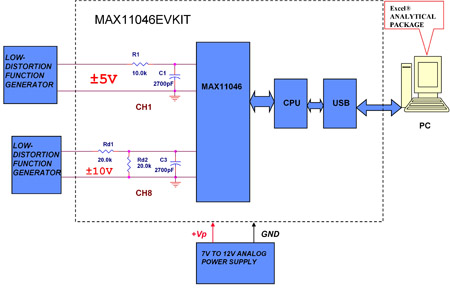
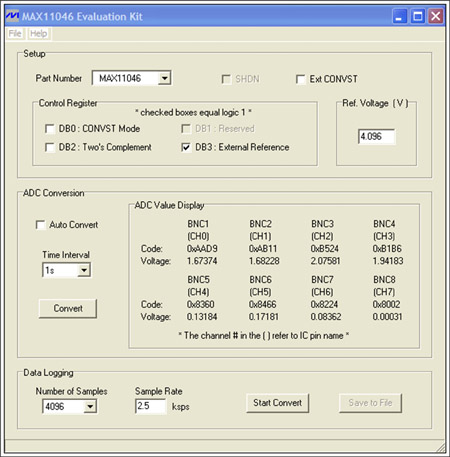
In Figure 3 the �5V signals from a function generator are connected to the MAX11046's channel 1 input by R1 and C1. The values of R1 and C1 must meet the ADC's acquisition time requirements and can be derived from Equation 2: R1MAX = (1/FSAMPLE - TCONV)/k(C1 + CSAMPLE) (Eq. 2) Where: R1MAX is the maximum source impedance; FSAMPLE is the sample rate; TCONV is the ADC's conversion time (e.g., 3μs for the MAX11046); K is the number of RC time constants needed to meet the ADC's required resolution (i.e., 12 time constants for a 16-bit ADC); and CSAMPLE is the internal sample capacitor (e.g., around 20pF for the MAX11046). From Equation 2, R1MAX is around 12.1k? at 2.5ksps and C1 = 2700pF. Therefore, the selected value of R1 = 10k? is within the design limits. The value of C1 = 2700pF is more than 100 times larger than CSAMPLE and, therefore, supplies more than sufficient charge to the internal sampling capacitor. The �10V signals from the function generator in Figure 4 are connected to the MAX11046's input channel 8 by the Rd divider and C2. Rd = 20k? and, therefore, according Table 2 should provide gain error around 0.12%. This performance meets the standard 0.2% accuracy measurement mandated by the popular European Union (EU) standard IEC 62053 for precision energy-metering equipment. The EV kit settings used for the above measurements are shown Figure 4.
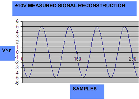
Results of the precision measurement using the settings required for the circuit in Figure 3 are shown in Table 3.
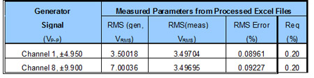
From Table 3, the measured RMS (meas) represents the measured and processed results of the generator's input RMS (gen). Results confirm that the measured RMS error of the conditioned circuits is approximately 0.09%, which comfortably meets the EU standard IEC 62053 precision requirement of 0.2% for energy-metering equipment.
High-performance multichannel, simultaneous-sampling ADCs like the MAX130x, MAX132x, and MAX11046 devices are especially useful in new DAS industrial applications. With properly selected signal conditioning, an interface circuit can exceed the EU standard requirements and advanced specifications for "smart" power-grid monitoring systems. For additional reading, see Maxim application notes, AN4639 and AN4595 www.maxim-ic.com


