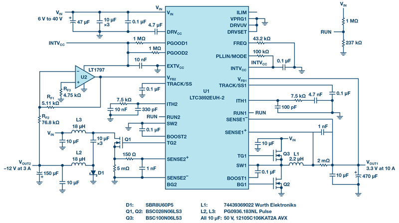
Figure 1. A solution for generating positive and negative voltages
Negative voltages are used to power an expanding number of LCD screens in automobile infotainment systems. Likewise, in industrial and railroad environments, negative rails satisfy the needs of instrumentation and monitoring applications. In all cases, the negative voltage rail must be produced from a positive source, but positive-to-negative ICs are not as readily available as buck controllers. Manufacturers are unlikely to have tested and qualified negative output converters, but probably already have a number of approved buck controllers, such as the LTC3892 dual output controller. To avoid the extra time and cost of testing a dedicated negative output converter, the LTC3892 dual output buck controller can be used to produce a negative output voltage with a Ćuk topology.
Dual Output Converter: –12 V at 3 A and 3.3 V at 10 A
The LTC3892 is a dual output controller, where one output can be used for a positive voltage and the other channel for a negative voltage, as shown in Figure 1. The input voltage range of this solution is 6 V to 40V, with VOUT1 equal to 3.3 V at 10 A and VOUT2 equal to –12 V at 3 A. VOUT1 is configured as a straightforward buck converter topology with powertrain components Q2, Q3, L1, and the output filter capacitors. No voltage divider is required at the VFB pin (tied directly to the output) to set the output to 3.3 V, as the LTC3892-2 features fixed 3.3 V or 5 V outputs set by the grounding or by tying VPRG1 to INTVCC, respectively.
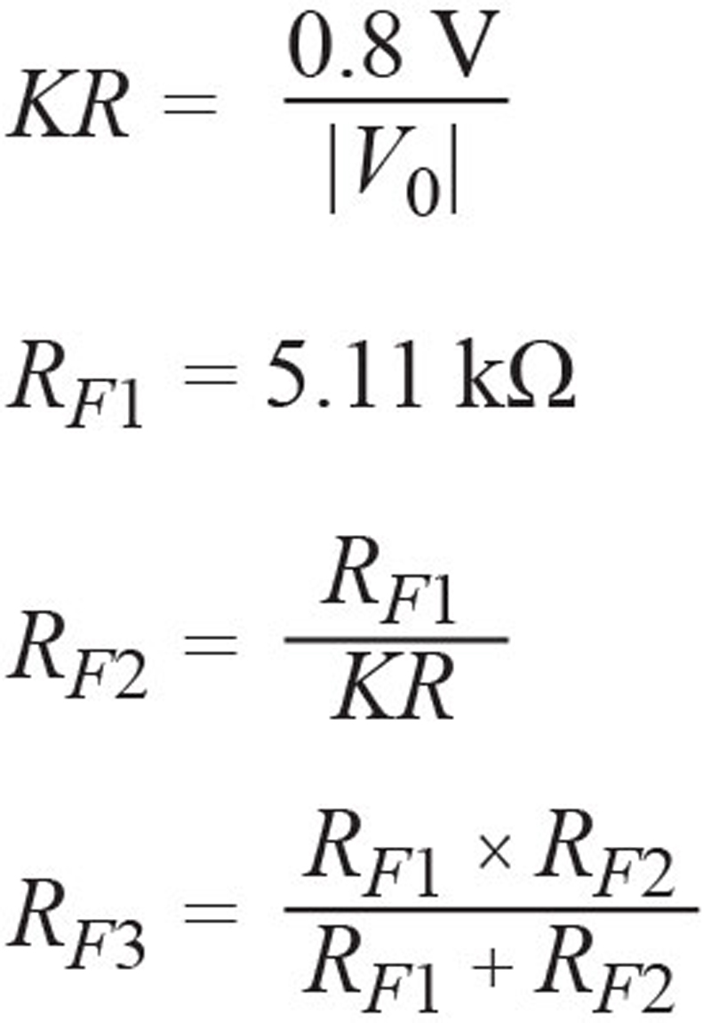
VOUT2 is a negative output voltage relative to GND. The opamp U2 (LT1797) is wired as a differential amplifier that is employed to sense the negative voltage and scale it to the 0.8 V reference of the LTC3892 error amplifier (EA). In this approach, both the EA of the LTC3892 and the opamp are referenced to system GND, which simplifies power supply control and functionality. The seed formulas for setting the negative output voltage are:
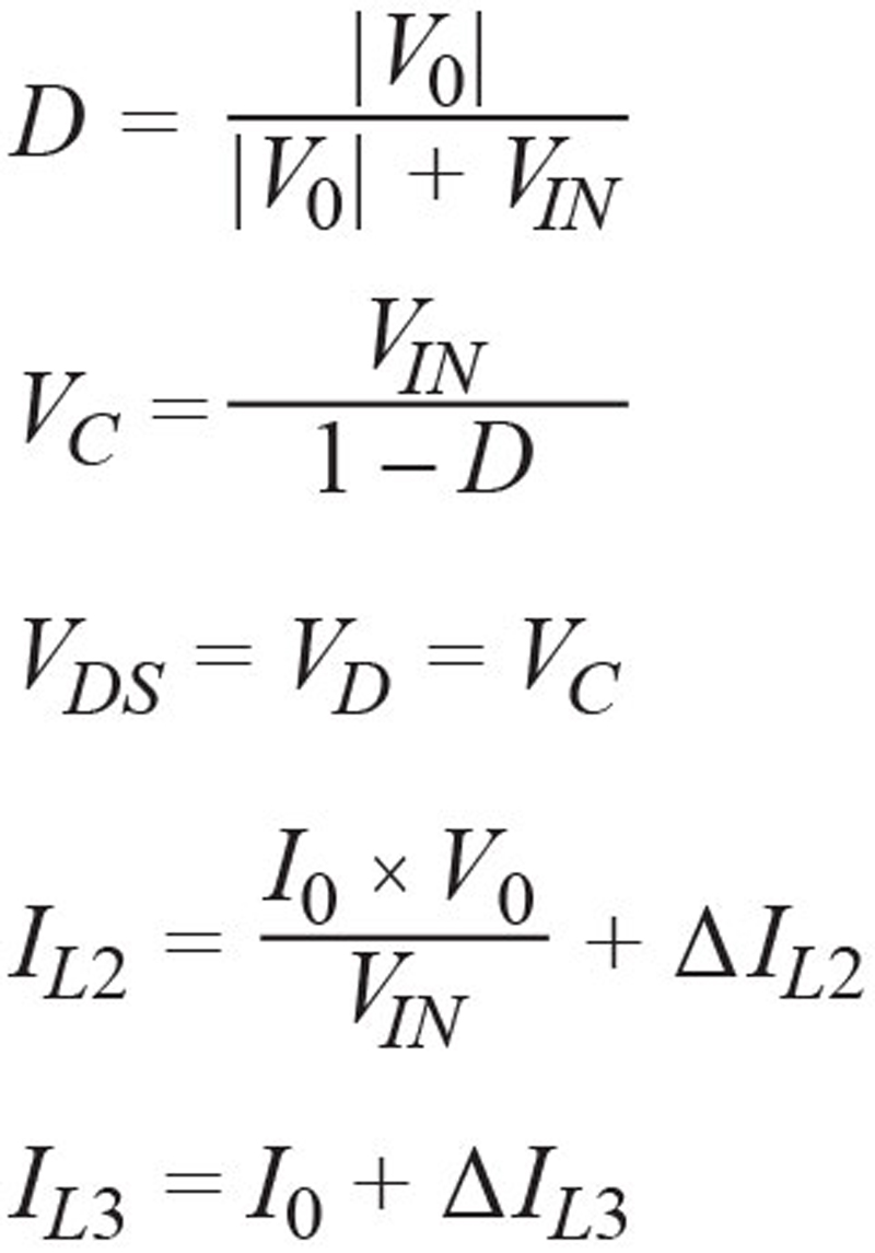
The VOUT2 employs a nonsynchronous Ćuk topology and includes power train components of Q1, D1, L2, and output filter capacitors. The Ćuk topology is widely covered in other technical literature, so it is not covered at length here. The stress on the power train components can be summed up by:
A DC2727A demonstration board was used to evaluate this solution, with the VOUT2 efficiency shown in Figure 2. This approach is also available in our LTspice® simulation model of the LTC3892-2.

Click image to enlarge
Figure 2. Efficiency for the negative output (VOUT2) at 14 V input
Conclusion
The LTC3892 is a versatile and flexible controller ostensibly designed for synchronous step-down conversion, but it can be used in a Ćuk topology to generate positive and negative voltages for automotive, industrial, and other applications.